8 Software
8.6
3D (Laser Line Detector) settings
This section describes how to the set the 3D properties. These properties are described in
Section 5.2.
1.
Set threshold value for laser line with property
Peak0_Threshold
(in category
LineFinder/Peak
0) (see also note in Section 5.2.3).
2.
Set scan area by setting the start row (
Peak0_3DY
in category
LineFinder/Peak0
) and the
height (
Peak0_3DH
in category
LineFinder/Peak0
) (see also Section 5.3.2).
3.
Set threshold for laser line width calculation. Its value must not be smaller than
Peak0_Threshold
.
4.
Set
LineFinder_Mode
(in category
LineFinder
) to
Mode_3Donly
or to
Mode_2Dand3D
. Note that
Mode_3Donly
should be selected for maximal frame rate.
5.
If
LineFinder_Mode
is set to
Mode_2Dand3D
then skip steps 6 to 8 and continue at step 9.
6.
The number of frames of the FrameCombine feature (
FrameCombine_NrOfFrames
) should be
set to a value that the resulting frame rate is below 200 for most applications (see also
Section 5.2.9). The resulting frame rate is the trigger rate divided by
FrameCombine_NrOfFrames
. In free running mode (
TriggerMode
=
Off
) the frame rate can be
read from the property
AcquisitionFrameRateMax
(in category
AcquisitionControl
). The
lower the resulting frame rate, the fewer interrupts are generated by the GigE driver and
the less load is produced on the computer’s CPU. E.g. if the trigger rate is 4000 fps then
FrameCombine_NrOfFrames
should be set to 20 or more.
7.
If FrameCombine is used, then the parameter
FrameCombine_Timeout
(in microseconds)
should be set (see also Section 5.2.9. The value should be higher than the longest time
between triggers, e.g. if the trigger rate is constant, then it could be set to twice the time
between triggers.
8.
If FrameCombine is used then
FrameCombine_Enable
should be set to
True
.
9.
Read the value of the parameter
HeightInterface
and set
Height
to this value.
8.7
Column FPN Correction
Due to the readout structure of the image sensors there is a column-wise fixed pattern noise
(FPN). The Column FPN Correction (ColCorrection) adds or subtracts a fixed value to a column.
These values are obtained by a calibration process. The ColCorrection of the camera was
calibrated at Photonfocus production facility.
8.7.1
Enable / Disable the Column FPN Correction
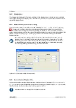
The Column FPN Correction can be enabled or disabled with the property
ColCorrection_Enable
(in category
Correction
/
ColCorrection
). By default the correction is enabled.
8.7.2
Calibration of the Column FPN Correction
The Column FPN Correction of the camera is correctly calibrated at Photonfocus production
facility. Although a new calibration is normally not required, you can recalibrate the Column
FPN Correction with the following instructions:
1.
Setup the camera to the mode where it will be usually used. (Exposure time, ...). The
width should be set to its maximal value. Due to the internal structure of the camera, best
performance of calibration will be achieved when calibrating under "real conditions".
104 of 127
MAN075 05/2017 V1.0
Содержание MV1-D2048-3D06 series
Страница 1: ...Photonfocus MV1 D2048 3D06 Camera Series 3D CMOS camera with GigE interface MAN075 05 2017 V1 0...
Страница 10: ...1 Preface 10 of 127 MAN075 05 2017 V1 0...
Страница 12: ...2 Introduction 12 of 127 MAN075 05 2017 V1 0...
Страница 16: ...3 How to get started 3D GigE G2 Figure 3 3 PFInstaller components choice 16 of 127 MAN075 05 2017 V1 0...
Страница 26: ...3 How to get started 3D GigE G2 26 of 127 MAN075 05 2017 V1 0...
Страница 32: ...4 Product Specification 32 of 127 MAN075 05 2017 V1 0...
Страница 66: ...5 Functionality 66 of 127 MAN075 05 2017 V1 0...
Страница 82: ...6 Precautions 82 of 127 MAN075 05 2017 V1 0...
Страница 120: ...12 Support and Repair 120 of 127 MAN075 05 2017 V1 0...
Страница 122: ...13 References 122 of 127 MAN075 05 2017 V1 0...
Страница 127: ...C Revision History Revision Date Changes 1 0 May 2017 First version MAN075 05 2017 V1 0 127 of 127...


