8 Software
1.
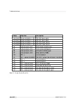
Identify the PLC notation of the desired input. A table of the PLC mapping is given in
Section 7.7. In our example, ISO_IN0 maps to A0 or Line0.
2.
Select a Signal Routing Block (SRB) that has a connection to the desired PLC input and
connect it to the PLC input. In our example, SRB PLC_I0 will be used as it has a connection
to Line0. To connect the SRB to input, set PLC_I<x> to the input. In the example, set PLC_I0
to Line0.
3.
Identify the PLC notation of the desired output. A table of the PLC mapping is given in
Section 7.7. In the example Q4 is the desired output.
4.
Connect the LUT that corresponds to the desired output to the SRB from step 2. In the
example, PLC_Q4 is connected to PLC_I0. Note that every LUT has the capability to connect
up to 4 inputs. In the example only the first input (PLC_Q4_Variable0) is used. The other
inputs are ignored by setting the PLC_Q4_Variable to Zero and the PLC_Q4_Operator to
Or for inputs 1 to 3.
5.
If a PLC output is used to connect to a camera trigger, then the corresponding Trigger
Source must be activated. In the example, TriggerSource is set to PLC_Q4 and TriggerMode
is set to On.
8.11.2
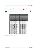
PLC Settings for ISO_IN0 to PLC_Q4 Camera Trigger
This setting connects the ISO_IN0 to the internal camera trigger, see Table 8.1 (the visibility in
the PF_GEVPlayer must be set to
Guru
for this purpose).
Feature
Value
Category
TriggerMode
On
AcquisitionControl
TriggerSource
PLC_Q4
AcquisitionControl
PLC_I0
Line0
<PLC>/SignalRoutingBlock
PLC_Q4_Variable0
PLC_I0_Not
<PLC>/LookupTable/Q4
PLC_Q4_Operator0
Or
<PLC>/LookupTable/Q4
PLC_Q4_Variable1
Zero
<PLC>/LookupTable/Q4
PLC_Q4_Operator1
Or
<PLC>/LookupTable/Q4
PLC_Q4_Variable2
Zero
<PLC>/LookupTable/Q4
PLC_Q4_Operator2
Or
<PLC>/LookupTable/Q4
PLC_Q4_Variable3
Zero
<PLC>/LookupTable/Q4
Table
8.1:
PLC
Settings
for
ISO_IN0
to
PLC_Q4
Camera
Trigger
(<PLC>
=
in
category
IPEngine/ProgrammableLogicController)
.
108 of 127
MAN075 05/2017 V1.0
Содержание MV1-D2048-3D06 series
Страница 1: ...Photonfocus MV1 D2048 3D06 Camera Series 3D CMOS camera with GigE interface MAN075 05 2017 V1 0...
Страница 10: ...1 Preface 10 of 127 MAN075 05 2017 V1 0...
Страница 12: ...2 Introduction 12 of 127 MAN075 05 2017 V1 0...
Страница 16: ...3 How to get started 3D GigE G2 Figure 3 3 PFInstaller components choice 16 of 127 MAN075 05 2017 V1 0...
Страница 26: ...3 How to get started 3D GigE G2 26 of 127 MAN075 05 2017 V1 0...
Страница 32: ...4 Product Specification 32 of 127 MAN075 05 2017 V1 0...
Страница 66: ...5 Functionality 66 of 127 MAN075 05 2017 V1 0...
Страница 82: ...6 Precautions 82 of 127 MAN075 05 2017 V1 0...
Страница 120: ...12 Support and Repair 120 of 127 MAN075 05 2017 V1 0...
Страница 122: ...13 References 122 of 127 MAN075 05 2017 V1 0...
Страница 127: ...C Revision History Revision Date Changes 1 0 May 2017 First version MAN075 05 2017 V1 0 127 of 127...


