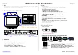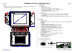
VL PPC 3000
3386_en_C
PHOENIX CONTACT
10/16
6.1
Power connection
A three-position, screw-type Combicon connector (MSTB
2,5/ 3-STF) is provided for connecting power to the VL PPC
3000.
Figure 5
Power connector
Connect a power source to the included power connector.
This connector supports wire sizes from 0.2 to 2.5 mm² (24
to 12 AWG). Torque the wire retaining screws in the
connector to 0.5 Nm (4.4 lb
f
-in.). Secure the connector to
the VL PPC 3000 chassis.
6.2
Serial communication
Settings in the BIOS configure the serial port (
X10:COM
)
to
function on the RS-232, RS-422, or RS-485 physical layer
(see “Configurable serial port” on page 16).
7
Operation
7.1
LED operation
Four LEDs are located on the bottom of the VL PPC 3000.
These LEDs provide operating information.
Figure 6
LED layout
Pin No.
Description
6
(FE)
Chassis ground
–
0 V DC
+
+19.2…28.8 V DC
NOTE:
The
6
of the VL PPC 3000 must be connected to
a functional ground.
NOTE:
The COM port cable must be less than 30 m when
the port is configured for RS-422/RS-485. Longer
cable lengths can be achieved by using an
external surge suppression device.
PWR
X7:US
B
X6:US
B
X5:US
B
X4:US
B
X3:ET
H
X2:E
TH
X1: PWR 24VDC
+
–
LED
Indication
Description
ERROR
Orange
Red
Indicates reduced performance
due to processor temperature.
Indicates an over-temperature
condition has caused the
processor to shut down.
RUN
Reserved for future use
HDD
Flashes
green
Indicates data storage (CF, HDD
or SSD) activity
PWR
Green
When 24 V DC is applied and the
power switch is turned on
ERROR
RUN
HDD
PWR
X7:U
X6:U
+
X8:DVI-D
LEDs


