VL PPC 3000
3386_en_C
PHOENIX CONTACT
12/16
Tray installation
1.
Orient the tray (5) so the lever pivot is on the power
connector side.
2.
With the lever (4) open, push the tray in until the drive
connector mates with the circuit board connector. This
cannot be seen but will be felt with increased resistance
as the connectors join.
3.
Pivot the lever in to secure the tray. Two notches on the
lever will seat into the chassis. Use a screwdriver to
rotate the knob (3) clockwise until tight to secure the
drive and tray assembly.
4.
Close the service door (1) before applying power to the
unit.
8.4
Real-time clock battery
The battery supplies power to the real-time clock (RTC) and
maintains the BIOS settings in the VL PPC 3000 when the
system is not connected to a 24 V DC power source. If
power is removed while the battery is discharged or
removed, any user-defined BIOS settings will be lost, and a
“CMOS checksum error” message appears once power is
restored.
To account for user-defined BIOS settings, it is
recommended that they be recorded through photos or a
separate document before the battery is depleted or
removed. Store the photos or documents on a different
device so they are accessible in the event of a boot failure.
The battery is type CR2032. The battery has a typical life of
five years and may require replacement.
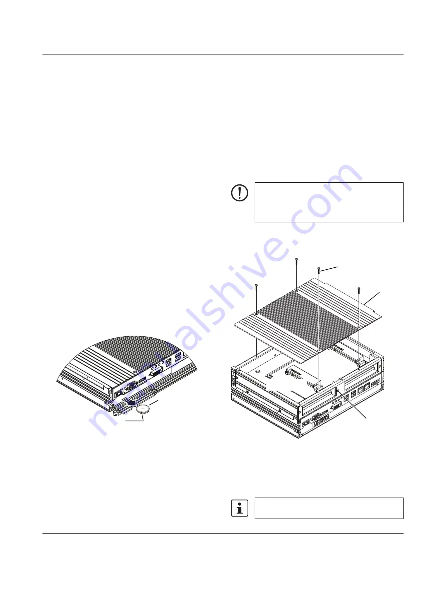
Figure 8
Inset RTC battery as shown
To replace the battery:
1.
Turn off the IPC and remove the power connector.
2.
Open the service door.
3.
Pull the tab attached to the battery to remove it from the
slot.
4.
Insert the new battery in the slot, making sure it is
oriented in the same way as the one removed (see
5.
Close the service door.
6.
Reconnect the power connector and apply power.
7.
During the boot-up process, press the <F1> to access
the BIOS settings.
8.
Update the BIOS configuration with any appropriate
user-defined requirements.
9.
Click the “Save and exit” option. The IPC will restart with
the appropriate changes.
8.5
Installing PCI cards
Installing a PCI card in the optional PCI slots is done as
follows:
1.
Ensure the card does not exceed the maximum
dimensions for the intended slot.
2.
Remove power from the unit.
Figure 9
Cover removal
3.
Place the unit on a soft cloth on a flat, horizontal surface
with the ribbed surface (cover) up.
4.
Remove the four Phillips-head screws (1) from the
cover (2) and remove the cover.
X10:
COM
ER
ROR
RU
N
HD
D
PW
R
X7:
USB
X6:
USB
X5:
USB
X4:
USB
X9:
DP
++
X3:
ETH
X2:
ETH
Positive (+)
CR2032 3 V
lithium battery
NOTE:
Use standard ESD precautions when removing or
installing PCI cards to avoid damage to the cards
and the VL PPC 3000.
Do not remove the tamper-proof screws (3).
X10
:COM
ERR
OR
RUN
HD
D
PW
R
X7:
USB
X6:USB
X5:U
SB
X4:U
SB
X9:
DP++
X3:
ETH
X2:
ETH
X1:
PWR
24V
DC
+
–
PCI Slot 0
PCI Slot 1
②
①
③


