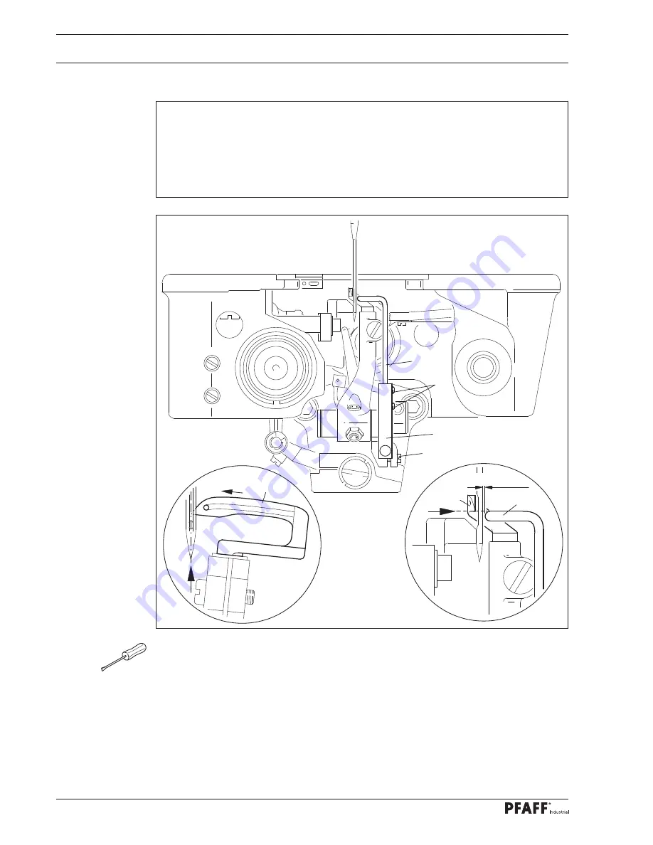
Pfaff 3811-15/65 Скачать руководство пользователя страница 98

Adjustment

98

Fig. 13 - 29

4

5

3

2

13

.05.29


Position of the front needle guard

Rule

When the looper point

is in the centre of the needle coming from the right side, the nee-

dle guard bar should 

4

1.  have a lateral clearance 

0.3 

-

 0.5 mm

 to the needle,

2.  stand parallel to the hook blade and

3.  the top edge should stand at the same height as the point of looper 

1. 


Move to the hook by turning handwheel

 1 

to its left reversal point.


Loosen the screws 

2.


Move the needle guard carrier 

3

 so that the needle guard bar 

4

 does not strike the looper


1

 in this position.


Gently tighten the screws 

2.


Turn the handwheel until the point of the looper 

is in the centre of the needle coming 

from the right.


Turn the needle guard carrier 

3

 according to rule 

1

.


Adjust the needle guard bar 

4

 (screws

 5

) according to rules 

2

 and 

3

1

0.3 - 0.5 mm

4

1

Содержание 3811-15/65

Страница 1: ...96 12 18 591 002 Instruction Manual engl 07 17 This instruction manual applies to machines from the serial number2 792 321 and software version 0352 013 onwards INSTRUCTION MANUAL 3811 3 55 15 65 16 6...

Страница 2: ...ding parts thereof is only permitted with our prior agreement and citation of the source PFAFF Industriesysteme und Maschinen GmbH Hans Geiger Str 12 IG Nord D 67661 Kaiserslautern This instruction ma...

Страница 3: ...2 Transportation within the customer s premises 14 5 03 Disposal of the packaging materials 14 5 04 Storage 14 6 Work Symbols 15 7 Operating Controls 16 7 01 Main switch 16 7 02 Pedal 16 7 03 Hand lev...

Страница 4: ...Cleaning the machine 60 12 03 Machine oil level 61 12 04 Cleaning lubricating the top feed joints 61 12 05 Checking setting the air pressure 62 12 06 Cleaning the maintenance unit air filter 62 12 07...

Страница 5: ...uit Diagrams 129 15 01 Pneumatic circuit diagram version 12 01 2006 91 196 282 95 129 15 02 Circuit diagrams 130 Reference list for circuit diagrams 91 191 493 95 130 16 Table Top 135 16 01 Table top...

Страница 6: ...Table of Contents Contents Page...

Страница 7: ...adhering to all the relevant safety requirements The machine must always be disconnected from the power supply by pressing the main switch or pulling out the mains plug when sewing tools are replaced...

Страница 8: ...tion for the owner operator This instruction manual is a part of the machine and must be made available to the operating personnel at all times The instruction manual must have been read before the in...

Страница 9: ...horised persons are located in the machine s hazard zone Any changes occurring on the machine which impair its safety must be reported to the owner operator immediately 1 05 02 Technical staff Technic...

Страница 10: ...of injury due to the motion of the take up lever Do not operate the machine without the finger guard 2 Risk of injury from the needle Do not operate the machine without the belt guard 3 and 4 Risk of...

Страница 11: ...n of fullness into one material layer The PFAFF 3811 16 65 is an integrated work station that is used in the upholstery industry for the incorporation of fullness into one material layer while simulta...

Страница 12: ...3811 15 65 3811 16 65 1 mm Sewing head dimensions Length approx 1250 mm Width approx 600 mm Height with spool holder approx 1700 mm Working air pressure 6 bar Air consumption 0 3 0 5 l work cycle Con...

Страница 13: ...rious plastics The electrical equipment consists of plastics and copper The machine must be disposed of in accordance with the locally valid environmental protection regulations with a specialised com...

Страница 14: ...Please ensure that the machines are only transported in a vertical position 5 03 Disposal of the packaging materials The packaging materials of these machines consists of paper cardboard and VCI flee...

Страница 15: ...med or important information in this instruction manual are emphasised by symbols The symbols used have the following meaning Note information Cleaning care Lubrication Maintenance repairs adjustment...

Страница 16: ...le Turning the main switch 1 switches the machine on and off Fig 7 01 1 7 02 Pedal With the main switch turned on 0 Neutral position 1 presser foot raised feed bridle tape 2 Sewing 1 Raise presser foo...

Страница 17: ...lever 1 raises the presser foot 1 7 04 Knee switch When sewing with fixed programs Actuating the knee switch 1 switches between two predefined fullness settings With programmed sewing By actuating the...

Страница 18: ...PFAFF 3811 3 55 and PFAFF 3811 15 65 By pushing down lever 1 the edge guide is switched on By lifting lever 1 the edge guide is switched off 1 Fig 7 05 7 06 Lever for releasing thread tension Press do...

Страница 19: ...ge value is called by pressing two adjacent numeric keys at the same time In the basic setting of the keypad the set range is divided into 15 sub steps from 0 to max The basic setting is e g after a c...

Страница 20: ...d up by pressing on the respective point on the monitor Pressing the respective function causes its immediate actuation or activation deactivation or another menu will appear e g for entering a value...

Страница 21: ...ns must be provided at the erection site see Chapter 3 Technical data The erection site must also have a firm and level subsurface and adequate lighting The table top is lowered for packaging purposes...

Страница 22: ...Mounting the upper V belt guard Screw in screws 1 and 2 Screw in screw 3 together with spacing bush 4 Slide belt guard halves 5 with their slots behind the heads of the screws 1 and 3 Gently tighten...

Страница 23: ...e lower V belt pulley Fig 8 05 8 01 05 Fitting the position sensor Attach the position finger 1 with the screws 2 Slide the synchroniser 3 onto the shaft so that the position finger 1 is positioned in...

Страница 24: ...he control unit Attach the following ground cables in order to discharge static electricity Securely attach ground cable from sewing head to ground point A Securely attach the ground cable from the co...

Страница 25: ...ure it with the enclosed nuts Fig 8 07 8 01 08 Mounting the control panel on the table top Mount control panel bracket 1 on table plate 4 with screws 2 and washers 3 Screw control panel 5 to control p...

Страница 26: ...s connected properly Never operate the machine if there are any differences The machine must only be connected to a grounded socket With the machine running the handwheel must turn towards the operato...

Страница 27: ...he electricity mains for all set up work by operat ing the main switch or by removing the mains plug Switch off the machine Risk of injury due to accidental machine start up Only use needles of the sy...

Страница 28: ...e adjusting the needle thread Switch off the machine Risk of injury due to accidental machine start up Thread the needle as shown in Fig 9 02 Adjust the needle thread tension by turning the knurled th...

Страница 29: ...ue to accidental machine start up Open the looper compartment cover and swing out the thread guide plate1 Thread the looper thread according to Fig 9 03 and 9 09 and pull it under guide plate 2 Use tw...

Страница 30: ...umber Select the desired program number Confirm the selection and leave the selection menu The selection of the program number determines the type of sewing see Chapter 10 Sewing Program number 0 Manu...

Страница 31: ...m number 0 Confirm the selection and leave the selection menu Enter the desired value using the corresponding arrow keys Or enter the current fullness value of a numeric key 0 15 of the keypad To do t...

Страница 32: ...Entering changing the template code Switch the machine on Call up Input mode Call up parameter 800 Call up the code number input menu Enter the code number using the numeric keypad code set at the fa...

Страница 33: ...onclude input The code input remains saved until the machine is switched off by the main switch Provided that the machine is not turned off all parameters can be accessed without re entering the templ...

Страница 34: ...h the machine on Call up Input mode Call up the service menu Call up the control panel functions Change the display contrast Switch the key tone off or on Never reduce the display contrast to such an...

Страница 35: ...ing position are displayed on the control panel during sewing and can be changed directly by means of the corresponding function such as the functions at the seam end the material type as well as the...

Страница 36: ...ntil the appropriate fullness level ap pears in the display without quilting approx 80 g m quilting approx 200 g m quilting approx 400 g m quilting Needle position raised If this function is on the ne...

Страница 37: ...t stitch position as well as the needle and foot positions apply across the entire area and can be changed at any time via the corresponding function Switch on the machine and select the program numbe...

Страница 38: ...enables the edge knife to be switched off via pedal function see Chapter 7 02 Pedal Presser foot up When this function is activated the presser foot is raised after sewing stops Presser foot down aft...

Страница 39: ...e types and line thicknesses The respective seam zone number parameter fullness and the functions at the seam end are displayed for the current seam zone The material type can be changed directly as w...

Страница 40: ...the seam program sequence see chapter 10 03 01 Program interruption Thread trimming When the function is activated thread trimming with the pedal function is possible optional When switched on this f...

Страница 41: ...the other functions as in manual sewing see Chapter 10 01 Manual sewing Or call up manual sewing 10 04 Error messages If an error occurs the text ERROR appears on the display together with an error c...

Страница 42: ...ameter value Change the value of the selected parameter see chapter 13 07 02 Example of a parameter input Software information Calls up information about the current machine software Create correct pr...

Страница 43: ...the program number and basic settings of the sewing program to be processed must first be selected 11 01 01 Basic settings for seam program input The basic settings are the same in the functions Crea...

Страница 44: ...am only with right seam Sewing program with left and right seam beginning with left seam End the input the basic settings and change to the input of the seam zone see Chapter 11 01 02 input via the Cr...

Страница 45: ...am input Change the actual are set length of the seam see Chapter 11 01 03 Entering the actual and actual length of the seam zone Change the fullness setting see Chapter 9 05 Entering fullness setting...

Страница 46: ...the first seam zone and change to the next seam zone End input and change to the input of the basic settings End the input and change to programmed sewing 11 01 03 Entering the actual and target lengt...

Страница 47: ...Input mode Call up Teach In function Make basic settings and complete with the Enter function see Chapter 11 01 01 Basic settings for seam program input The following displays and functions appear on...

Страница 48: ...Chapter 11 01 05 Seam zone input when pro gramming the seam A stitch condensation is defined when entering the functions for the end of the seam zone is performed on completion of the seam program en...

Страница 49: ...and off Enter or change the number of stitches for the seam zone via numeric input or by using the arrow keys Activate or deactivate automatic sewing stop at the end of the seam zone Activate or deact...

Страница 50: ...ved under program number 4 with the comment PROG Switch the machine on Call up Input mode Enter the Create correct seam program function and enter the program number 4 Press the key until the correspo...

Страница 51: ...er value 0 for the fullness Call up the seam zone menu Enable the seam zone relaying via the knee switch Complete the input of the seam zone Change to the second seam zone In the second seam zone a ta...

Страница 52: ...ntry of the target actual length The number of stitches 37 and the value for the fullness setting 70 are determined from the values entered Since conversion must be based on whole stitches the value f...

Страница 53: ...seam zone four it should be worked without a fullness setting the end of the seam zone should be executed by the pedal function the functions trim thread and lift sewing foot should be enabled Enter...

Страница 54: ...t TEACH Sewing direction Seam zone 1 Gather setting 0 End of section Knee switch Seam zone 2 Gather setting 17 Stitch count 49 Seam zone 3 Gather setting 38 Stitch count 31 Seam zone 4 Gather setting...

Страница 55: ...the keypad and numeric keypad Conclude the comment input Switch to the input of seam zone 1 The first seam zone should be worked with no gathering value 0 or value 0 with gathering Sew the first seam...

Страница 56: ...s for the 3rd to 8th seam zones as described for zone 2 observe the respective values in the diagram and sew the individual seam sections Change to the ninth seam zone Enter value 0 with gathering Sew...

Страница 57: ...tting 12 Enter value 12 Sew the tenth seam zone using the pedal function Define the end of the seam zone via the pedal position 2 see Chapter 7 02 Pedal Activate End program function Complete the inpu...

Страница 58: ...ard it will take up to 20 s until the SD card is recognised as inserted Switch the machine on Call up Input mode Call up program management SD card and machine memory are read Description of the funct...

Страница 59: ...achine data can be copied or deleted on the SD card Format the SD card The SD card is formatted after pressing FORMAT A prompt for confirmation is displayed before the SD card is formatted The card is...

Страница 60: ...ne start up The following tasks are recommended during single shift operation to avoid operational errors Tilt the machine backwards Clean the hooks and hook area daily or more often during continuous...

Страница 61: ...density of 0 865 g cm3 at 15 C We recommend PFAFF sewing machine oil Order No 280 1 120 144 Fig 12 02 1 12 04 Cleaning lubricating the top feed joints Clean the areas marked in the illustra tion once...

Страница 62: ...1 Unscrew the filter 2 Clean filter 2 with compressed air or isopropylalcohol order no 95 665 735 91 Screw in the filter 2 and screw on the water tank 1 Fig 12 05 2 1 1 2 12 05 Checking setting the a...

Страница 63: ...tenance and Care 63 12 07 Cleaning the blower air filter Remove the cover 1 Remove the filter element and blow it out with compressed air Insert the cleaned filter element and fit the cover 1 Fig 12 0...

Страница 64: ...letely adjusted Both the preceding and following chapters must be observed if only specific individual work steps are carried out The screws and nuts indicated in brackets are fastenings for machine p...

Страница 65: ...in the corresponding adjustment hole and press it down Turn the handwheel slightly back and forth until the adjustment pin engages the rear crank cutout blocking the machine Adjustment hole 1 top dea...

Страница 66: ...he machine on Call up Input mode Call up Service Turn the handwheel in the sewing direction to determine the number of increments per revolution this maximum value appears in the display under POS bef...

Страница 67: ...in the direction of rotation until the needle point approaching from above is flush with the upper edge of the needle plate Conclude the input Switch the machine off 13 06 01 02 With P320 ED control S...

Страница 68: ...this key the machine performs 3 stitches at a speed of 360 r p m Call up Input mode Call up parameter 301 Turn the handwheel in the direction of rotation until the needle point approaching from above...

Страница 69: ...g direction 2 The clearance between the needle 5 and the front edge of the needle hole should be approximately 0 8 mm Loosen the screws 1 and 2 Move needle bar frame 3 according to rule 1 and tighten...

Страница 70: ...edle height Rule 3811 3 55 3811 15 65 16 65 3 4 1 5 3 4 1 5 X When the needle bar is at t d c Needle bar adjustment hole 1 the clear ance X between the needle plate and the needle point should be 11 m...

Страница 71: ...rew 1 nut 2 remove the stitch length limiting lever Set the stitch length to 0 using the adjusting lever Loosen screw 4 until the crank 5 is difficult to twist on the shaft Whilst continuously turning...

Страница 72: ...0 and the ad justment gauge 1 attached Fig 13 05 3 2 Set the stitch length to 0 Fit adjustment gauge 1 Loosen screw 2 until crank 3 is difficult to turn on the shaft Whilst continuously turning the ha...

Страница 73: ...t gauge 8 when actuating the roller 5 the main and differ ential feed should not move Fig 13 06 6 7 1 2 Slightly loosen screws 1 and 2 4 screws Move the needle bar to 0 8 before t d c and set the stit...

Страница 74: ...ole 1 the cutout of the eccentrics 3 and 4 must point vertically downwards Loosen screws 1 and 2 4 screws Move the needle bar to t d c Turn the eccentrics 3 and 4 according to the instructions and tig...

Страница 75: ...djustment hole 1 the cutout of the eccen trics 3 and 4 must point vertically downwards Loosen 2 screws 1 Move the needle bar to t d c Turn the eccentric 2 according to the instructions and tighten scr...

Страница 76: ...djustment hole 5 the cutout of the eccentric 2 must point vertically downwards Loosen two screws 1 Move needle bar to 5 5 mm before t d c Turn the eccentric 2 according to the instructions and tighten...

Страница 77: ...parallel at 1 9 mm above the stitch plate 2 Both feed dogs lie in the centre of the stitch plate cutout and 3 stand at a clearance of 4 mm apart Move the needle bar to t d c and set the largest stitch...

Страница 78: ...entre of the stitch plate cutout and stand at a clearance of 4 mm apart Set the largest stitch length and move the main feed dog to its highest position Set carrier 1 of the main feed dog by turning t...

Страница 79: ...tment gauge 4 attached the vibrating presser should not perform any sliding movement The stitch length limiting lever screw 1 in Chapter 13 06 04 zero position of the main feed dog must be lifted Set...

Страница 80: ...c Adjustment hole 4 there should be a clear ance of approximately 16 5 mm between the eye of connecting rod 2 and the machine housing 3 Move needle bar to 0 8 before t d c Loosen screw 1 Adjust connec...

Страница 81: ...bottom feed Raise the hand lever 1 Move vibrating presser 2 to its upper reversal point by turning the handwheel Lift pressing bar 3 and the push the 5 mm thick part of the adjustment gauge 4 order no...

Страница 82: ...ing direction to the centre of the sewing foot cut out and tighten screw 14 Loosen screw 15 Connect lever 16 to connecting rod 17 using the eccentric pin screw 12 in doing so set the eccentric pin 11...

Страница 83: ...e bar position 0 8 mm before t d c adjust ment hole 4 lever 4 should not move when lever 2 is actuated Loosen two screws 1 While continuously moving the lever 2 up and down set eccentric 3 so that the...

Страница 84: ...the elongated hole in the lever 7 until they abut To preset the clearance between the vibrating presser 2 and the sewing plate move the lever 8 screw 9 Turn the eccentric pins 10 screw 11 in accordanc...

Страница 85: ...With a stitch length regulation of 4 and attached setting gauge 3 the vibrating presser should fit against the bottom feed once this has reached the upper surface of the sewing plate coming from below...

Страница 86: ...ut 5 according to rule 2 1 5 4 6 3 2 x 1 The lower rocker stop should be set so that the stitch length is 2 2 mm x 22 mm for 11 penetrations 2 For the same stitch length the screw 4 should lightly abu...

Страница 87: ...Home position of the differential setting Rule 3811 3 55 3811 15 65 16 65 Fig 13 19 1 9 3 8 7 5 1 6 2 4 0 11 12 13 14 15 10 2 3 5 4 6 1 mm 2 4 1 With fullness setting 0 stitch length regulation 2 2 a...

Страница 88: ...3 55 Rule With stitch length regulation and activated button 15 cylinder 4 completely extended the stitch length should be 3 mm Fig 13 20 Set stitch length 3 lever 1 Switch the machine on and press b...

Страница 89: ...otion Rule When the needle bar is at t d c Needle bar adjustment hole 1 the cutout of the eccentric 2 must point vertically downwards Loosen two screws 1 Move the needle bar to t d c Turn the eccentri...

Страница 90: ...osition a 1 2 Insert a new needle Turn the handwheel until the hook point are on the left side of the needle coming from the right In this position tighten the clamping screw Order no 08 880137 00 ont...

Страница 91: ...er 7 abuts against the looper adjustment gauge 9 Fig 13 23 8 2 4 3 5 Disassemble the stitching plate and bottom feed Place adjustment gauge 1 Order No 61 111 642 19 on the stitch plate support Set loo...

Страница 92: ...5 mm 91 169 614 05 0 8 mm 91 169 615 05 1 2 mm 91 170 694 05 Place the looper adjustment 9 order no 61 111 643 06 on the left edge of the cover plate guide see arrow and push against the looper Move l...

Страница 93: ...24 2 1 2 Turn the handwheel until the hook point reaches the left side of the needle from the right side Adjust looper unit 1 screws 2 according to the rule If the clearance of 0 1 mm is not achieved...

Страница 94: ...needle Move looper 1 to its right reversal point by turning the handwheel Place the feeler gauge 3 6 of the looper adjustment gauge 2 order no 61 111643 0 6 with its notch in the feeding direction aga...

Страница 95: ...e of the needle coming from the right side the top edge of the needle eye should be 1 0 1 2 mm below the under edge of the looper Turn the handwheel until the hook point reaches the left side of the n...

Страница 96: ...e When the needle bar is in b d c Needle bar adjustment hole 3 the vertical surface of the needle guard 1 should cover approximately 2 3 of the needle eye Move the needle bar to b d c Move needle guar...

Страница 97: ...touches the side of the needle coming from the right side the nee dle guard 3 should lightly touch the needle Turn the handwheel until the hook point is on the right side of the needle Adjust the bra...

Страница 98: ...nd at the same height as the point of looper 1 Move to the hook by turning handwheel 1 to its left reversal point Loosen the screws 2 Move the needle guard carrier 3 so that the needle guard bar 4 doe...

Страница 99: ...13 06 30 Looper avoiding motion guard Rule Eccentric 3 should not touch the guard 1 when moving Align the protective plate 1 screws 2 accessible through the adjustment holes accord ing to the rule Fi...

Страница 100: ...d the needle bar frame 3 2 The needle thread puller 2 should be able to move freely in the centre of the slot and not strike either at the top or the bottom reversal point Make screw 1 accessible by t...

Страница 101: ...hould be at the same height 2 The thread guide 2 should be screwed on vertically and in the centre of the elongated hole Move the needle bar to b d c After loosening the needle thread controller screw...

Страница 102: ...e 29 mm 2 The front edges of the thread controller 3 and thread regulator 1 should have approxi mately 8 mm clearance Adjust the slack thread regulator 1 screws 2 according to rule 1 Adjust the thread...

Страница 103: ...n the front edge of the thread controller 4 Move the needle bar to t d c Twist the looper thread puller 1 screw 2 according to rule 1 in doing so ensure that the yoke of the looper thread puller 1 sta...

Страница 104: ...the vibrating presser and the presser foot should be set so that the material being sewn is optimally transported at every sewing speed Adjust the sewing foot pressure on screw 1 nut 2 according to th...

Страница 105: ...36 13 07 Adjusting the edge cutting equipment 13 07 01 Cutting movement Rule When the needle bar is at t d c Needle bar the knife should be in its upper reversal point Turn the eccentric 1 screw 2 acc...

Страница 106: ...Adjustment 106 Fig 13 37 13 07 02 Zero point Rule With cylinder 3 completely extended the knife should not move when the handwheel is turned Turn crank 1 screws 2 according to the rule 1 2 3...

Страница 107: ...13 38 13 07 03 Cylinder drive home position Rule With cylinder 3 fully retracted the nut 4 should have a clearance of 10 mm from the lower edge of cylinder 3 Adjust stop 1 screw 2 according to the ru...

Страница 108: ...9 13 07 04 Knife height Rule At the knife 1 reversal point the front edge of the knife 1 should be approximately 0 5 mm below the upper edge of the stitch plate Adjust the knife 1 screw 2 according to...

Страница 109: ...sewing direction Rule 1 The knife 3 should abut the stationary knife with slight pressure 2 In doing so knife 3 must not make contact with the sewing plate Adjust the knife to its lowest position and...

Страница 110: ...plate 1 2 The guide rails 5 should be parallel to carrier plate 1 3 The thread catcher 4 should move easily with a little play Remove carrier plate 1 screws 2 Loosen the screws 3 Move the thread catch...

Страница 111: ...tion the ball pins 1 should 1 be in the centre of the actuator 5 and 2 have a clearance of 0 5 mm from the root of actuator 5 Set ball pins 1 vertically Adjust the carrier 2 screws 3 according to rule...

Страница 112: ...hen the thread trimmer device is in neutral position the tip of the thread catcher 4 should have a clearance of 4 mm from the centre of the needle Move the thread trimmer to the neutral position Turn...

Страница 113: ...tion there should be a clearance between the securing curve 2 and the guide roller 3 of 0 5 1 0 mm Fig 13 44 Loosen screws 1 until the securing curve is difficult to turn on its shaft Move the needle...

Страница 114: ...on release Rule With the cylinder fully actuated there should be a clearance between the upper edge of the slot in plate 1 and the guide pins 3 of approximately 0 5 mm Fully extend the thread trimmer...

Страница 115: ...n doing so the threads must be flawlessly cut and clamped Place some material under the presser foot and sew a couple of stitches Remove the cover plate 1 Set the needle position shown in Chapter 13 0...

Страница 116: ...ensor Rule After trimming the thread the machine should be at 0 3 0 4 mm before t d c Position the needle bar Adjust position sensor 1 screw 2 according to the operating manual for the motor see also...

Страница 117: ...which the individual parameters can be directly called by pressing the desired function All parameter groups or also individu al ones can be protected by a code against unauthorised access Select para...

Страница 118: ...13 09 02 Example of a parameter input Switch the machine on Call up Input mode E g call up parameter 113 signal tone sounds at seam zone change on off E g signal tone when switching on value ON Concl...

Страница 119: ...ife at pedal posi tion 2 OFF ON OFF 212 Change the speed for fullness OFF ON OFF 213 Program termination at pedal position 2 OFF ON OFF 214 Reference movement for fullness adjust ment after thread tri...

Страница 120: ...aximum machine speed 1 42 42 711 Maximum motor speed 1 42 42 712 Positioning speed 3 25 18 713 Acceleration ramp 1 50 35 714 Braking ramp 1 50 P320 MS 30 P320 ED 10 715 Reference position 0 127 0 716...

Страница 121: ...up Parameter Description Setting range Setting range 8 807 Access rights for function group 700 0 1 1 808 Access rights for function group 800 0 1 1 809 Programming access rights 0 1 1 810 Input acces...

Страница 122: ...ng initialisation 65 Excess current directly after mains on 66 Short circuit 68 Overcurrent in operation 69 No increments 70 Motor blocked 71 No incremental plug 73 Faulty motor operation 74 Increment...

Страница 123: ...r initialisation xxx Sewing motor controller error byte see Chapter 13 08 Sewing motor error E003 Section E004 Section end E005 Pedal activated when machine turned on E006 Rapid job keypad CAN E007 Ra...

Страница 124: ...table O1 Lift sewing foot O1 1 and O1 2 O2 Thread trimmer O2 1 and O2 2 O3 Tape brake O4 Stitch length 4 mm 3 mm O5 free O6 Stitch condensation O7 Edge trimmer O8 free O9 free O10 free O11 Clean thre...

Страница 125: ...he service menu and call up the input mode Sewing mode Quit the service menu and call up the sewing mode Set reset the outputs Select the desired output using the arrow functions and set Function 1 or...

Страница 126: ...3 15 Run cold start Switch the machine on Call up Input mode Call up the service menu Run cold start After a cold start all programmed values are reset to their as delivered status All seam programs a...

Страница 127: ...nection between the PC serial interface or corresponding USB adapter and the machine control unit RS232 by loosening the control pan el connector Switch on the PC and start the PFP boot program Select...

Страница 128: ...Internet download the parts list can also be requested as a hard copy under order no 296 12 18 591 11 330 085 15 11 108 174 25 PFAFF 3811 15 65 16 65 System 4463 35 PFAFF 3811 3 55 System 4463 KKD 91...

Страница 129: ...f r Fadenabschneid Einrichtung Zylinder f r Bandabschneid Einrichtung Zylinder f r verk rzte Stichl nge 3811 15 65 16 65 Zylinder f r Kantenscheid Einrichtung 3811 16 65 Cylinder for edge trimmer dev...

Страница 130: ...ncoder control unit XR3 Incremental encoder sewing motor XS3 Synchronizer PD3 X4B Stepping motor Fullness SM1 X5 Inputs X8 Sewing motor X11A CAN Interface key field X11B Pedal nominal value transmitte...

Страница 131: ...09 2005 91 191 493 95 Part 1 Plug Plug Plug Sewing head Table stand Sewing lamp Mains Motor Moto r Synchro Sewing motor Sewing motor Rotor position encoder Synchronizer Synchro Pedal nominal value tr...

Страница 132: ...Circuit Diagrams 132 91 191 493 95 Part 2 Version 01 09 2005 Circuit diagram Interface Control device Stepping motor Fullness Key field Phase Phase Phase Phase Phase Phase Phase Phase...

Страница 133: ...Circuit Diagrams 133 Circuit diagram Version 01 09 2005 91 191 493 95 Part 3 Program knee switch Initiator reference Start inhibitor Inputs Control device Initiator Initiator Initiator Knee switch...

Страница 134: ...Circuit Diagrams 134 91 191 493 95 Part 4 Version 01 09 2005 Circuit diagram Control device Outputs Lift presser foot Thread trimmer Tape brake Stitch length Edge trimmer...

Страница 135: ...135 16 Table Top 16 01 Table top cutout Table top assembly deep...

Страница 136: ...chnung 906 4001 117 Lage des Bandabzugger tes Lage der N hleuchte 0 5 2x 0 5 2x 0 1 Lage des EMT Gestells 906 3700 000 bei Montage bohren Lage des Bedienfeldtr gers 95 774 819 75 13 5 3x 34 3x 40 R 2...

Страница 137: ...Notes...

Страница 138: ...riesysteme und Maschinen GmbH is an authorised licensee of the PFAFF trademark PFAFF Industriesysteme und Maschinen GmbH Hans Geiger Str 12 IG Nord D 67661 Kaiserslautern Tel 49 6301 3205 0 Fax 49 630...

Отзывы: