Pfaff 3588-05/020 Скачать руководство пользователя страница 138

138

Adjustment

13

.07.02 

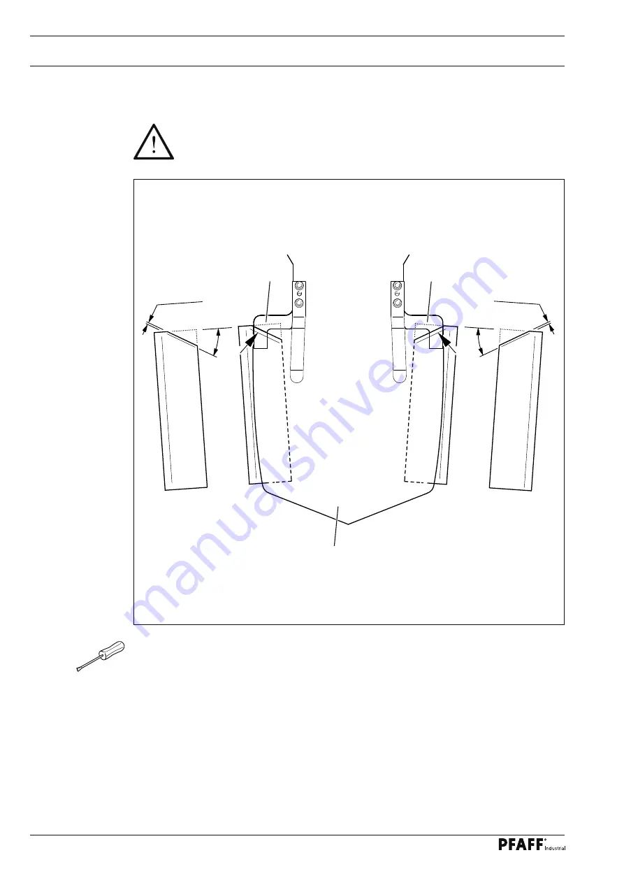
Slanting the lateral folder plates

Do not begin with this work process until the adjustments in chapters 

13

.

06

.12 

Aligning the seam in relation to the pocket

 and 13.06.13 

Seam backtack dis-

tance 

have been carried out!


With the folder plates fully extended, transfer the front edges of the stops 

1

 and the 

outer edge of the pocket plate 

2

 to the lateral folder plate.


Trace slanted edge of 

30°

.


Work the folder plate up to 

1

 - 

2


mm

 before the trace.


Round off the edges of the folder plate and polish.

2

1

1

1 - 2 mm

30°

30°

1 - 2 mm

Fig. 13 - 46

Содержание 3588-05/020

Страница 1: ...6 12 19 094 002 Betriebsanleitung engl 08 12 This instruction manual applies to machines from serial number 2 760 129 and software version 0380 003 0381 003 onwards INSTRUCTION MANUAL 3588 05 020 15 0...

Страница 2: ...cations Reprinting copying or translation of PFAFF instruction manuals whether in whole or in part is not permitted without our prior permission and not without written indication of the source PFAFF...

Страница 3: ...portation inside the customer s premises 14 5 03 Disposal of packing materials 14 5 04 Storage 14 6 Explanation of symbols 15 Register 03 15 7 Controls 17 7 01 On off switch 17 7 02 Stopptaster 17 7 0...

Страница 4: ...01 Automatic sewing mode 48 10 02 Manual sewing mode 49 10 03 Sewing with sequences 51 10 04 Program interruption 52 10 05 Error messages 53 11 Input 54 11 01 Overview of the functions in the input mo...

Страница 5: ...roller lever radial position of the control cam 107 13 05 16 Thread catcher height 108 13 05 17 Thread catcher position and knife height 109 13 05 18 Knife pressure 110 13 05 19 Bobbin thread clamp s...

Страница 6: ...8 149 14 Control 151 14 01 Basic setting Diagnosis Pin assignment 151 14 01 01 Basic control unit A20 151 14 01 02 Sewing drive A22 153 14 01 03 Stepping motor drive A21 155 14 01 04 Stacker motor dri...

Страница 7: ...changing sewing tools e g needle roller presser needle plate and bobbin when threading the machine when leaving the machine unattended and during mainte nance work the machine is to be separated from...

Страница 8: ...ailable to the operating staff at all times This instruction manual must be read before the machine is operated for the first time Both operating and technical staff must be instructed on the safety d...

Страница 9: ...occurring on the machine which may affect its safety must be reported to the user immediately 1 05 02 Technical staff Technical staff are persons who have been trained in electrical engineering electr...

Страница 10: ...ry by hurled objects Do not operate the machine without protective covers 1 2 3 4 and 5 Danger of crushing between moving parts of the pneumatic or feed systems Do not operate the machine without take...

Страница 11: ...ll uses of this machine which have not been approved of by the manufacturer are considered to be inappropriate The manufacturer cannot be held liable for any damage caused by the inappropriate use of...

Страница 12: ...0 250 x 250 mm PFAFF 3588 15 020 280 x 280 mm Storage capacity 5 000 000 stitches Working air pressure min 6 bar Air consumption approx 25 l cycle Ambient temperature 85 rel humidity condensation not...

Страница 13: ...d various plastic materials The electrical equipment comprises plastic materials and copper The machine is to be disposed of according to the locally valid pollution control regula ti ons if necessary...

Страница 14: ...e machines are only transported in an upright position 5 03 Disposal of packing materials The packing materials of this machine comprise paper cardboard and VCE fibre Proper dis posal of the packing m...

Страница 15: ...struction manual work to be carried out or important information is accentuated by symbols These symbols have the following meanings Note information Cleaning care Lubrication Maintenance repairs adju...

Страница 16: ......

Страница 17: ...f switch By turning on off switch 1 the power supply to the machine is switched on or off 1 7 02 Stopptaster By pressing the stop switch 1 the com plete work cycle is stopped see chapter 10 04 Program...

Страница 18: ...be adap ted to the various requirements for loa ding the workpiece The adjustment is made with parameter 113 and 114 see Chapter 13 10 02 Parameter List With the needle strip engaged needles up there...

Страница 19: ...n both double start keys 1 are activated simultane ously the entire program sequence is started The double start keys 1 also are used to continue the program after the bobbin has been replaced or the...

Страница 20: ...or texts are framed these show functions which can be selected by pressing the appropriate position on the monitor By pressing the corresponding function this is carried out or switched on or off imme...

Страница 21: ...n there must be a stable and horizontal surface as well as suitable electricity and compressed air supplies see chapter 3 Specifications Lift the machine with a forklift from the shipping pallet For m...

Страница 22: ...ool holder according to Fig 8 03 Fig 8 03 8 02 Removing the transit support bracket Before the machine is commis sioned transit support bracket 1 must be removed Transit support bracket 1 serves to se...

Страница 23: ...any damage Have skilled personnel check if the machine can be operated with the available mains voltage Do not operate the machine if there is any discrepancy The machine may only be connected to an...

Страница 24: ...pter 8 09 Checking adjusting the zero points To switch off the machine turn main switch 3 to position 0 Description of other functions on the display Input menu This function is used to call up the in...

Страница 25: ...sd card slot in the control panel Socket 2 is for connecting the program ming system OSCA With OSCA existing CAD data records can be used to gene rate seam programs Call up the settings menu 2 8 07 S...

Страница 26: ...panel Switch on the machine Call up the input mode Select the service menu Select control panel functions Change the display contrast Switch the key tone off or on Never reduce the display contrast to...

Страница 27: ...ssioning the machine and after changing the control unit or one of the initiators of the sewing jig feed unit it is necessary to adjust the zero points Call up the input mode Select the service menu C...

Страница 28: ...table when the sewing jig is in this position If necessary correct the position of the sewing jig accordingly using the direction sym bols Save the setting If this position is altered the needle posi...

Страница 29: ...n the needle bar with screw 2 By turning balance wheel 3 check whether adjustment pin 1 can be guided into the hole in the sewing jig If necessary correct the position of the sewing jig accordingly us...

Страница 30: ...tion Check whether adjustment pin 1 can be guided into the adjustment hole of the sewing jig and the pocket plate If necessary correct the position of the sewing jig accordingly using the direction sy...

Страница 31: ...31 Mounting and commissioning the machine Move the machine to its basic position the machine is ready for operation...

Страница 32: ......

Страница 33: ...Inserting the needle Switch the machine off Danger due to unintentional starting of the machine Only use needles from the sys tem intended for the machine see Chapter 3 Specifications Raise the needle...

Страница 34: ...in fills up during sewing The tension of the thread on bobbin 1 can be adjusted with knurled screw 4 The bobbin winder stops automatically when bobbin 1 is full Remove the filled bobbin 1 and cut the...

Страница 35: ...see Chapter 7 04 Double start keys Program cycle continues or Call up the change bobbin function Changing the bobbin adjusting the bobbin thread tension see following section Press the double start ke...

Страница 36: ...e thread tension Switch on the machine Lower the presser foot 1 and open thread trapper 2 Thread the needle thread as shown in the above illustration Adjust the needle thread tension by turning knurle...

Страница 37: ...tion This function opens the menu for selecting or configuring the sequence see Chapter 9 06 Selecting configuring the sequence Parts program This function opens the menu for entering the parts progra...

Страница 38: ...mber Call up the menu for entering the sequence Select the desired sequence number 0 9 using the number block Confirm the selection and quit the selection menu Description of the other functions Clear...

Страница 39: ...e sequence from existing seam programs by entering the program numbers on the number block The cursor in the window shows which seam program has been taken out of the group or at which position a new...

Страница 40: ...rame ters 116 to 119 Individual programs can also be allocated to slide configurations with parameter 115 Switch on the machine Call up the input menu Call up the parameter input function Select param...

Страница 41: ...g jig which could cause the needle to break If the machine is equipped with this optional device the JIG MONITOR function must be ac tivated and a jig code must be entered in the sewing program in ord...

Страница 42: ...particular way on carrier 2 Bit assignment Example decimal number 3 5 is equal to the binary combination 1 1 0 0 1 0 1 0 tens place 3 ones place 5 Ones place Tens place Bit 0 Bit 4 Bit 1 Bit 5 Bit 2...

Страница 43: ...er sewing the number of bobbin thread stitches the machine stops auto matically for changing the bobbin Description of the other functions Clear on number block This function sets the input value at 0...

Страница 44: ...ng jig must match and always be used together If the wrong combination of parts and seam program is used the machine may be damaged seriously Fig 9 06 5 6 7 1 3 2 4 Switch on the machine Call up the i...

Страница 45: ...sen screw 6 and remove folder set 7 Insert the folder set which matches the pocket plate and the sewing jig tighten screw 6 and screw the compressed air supply 5 back on Conclude the part set change M...

Страница 46: ...re cut pocket part onto the pocket plate according to Fig 9 07 Menu combination Basic position pocket plate front plain materialfabric off Slide the pre cut pocket part onto the pocket plate according...

Страница 47: ...ion are shown on the display Automatic ope ration is standard but it is possible to switch to manual operation when setting up and checking operating sequences Before production the following conditio...

Страница 48: ...ard stitch length The current stitch length is shown in the symbol Maximum speed This function opens the menu for entering the maximum speed The current maximum speed is shown in the symbol Input menu...

Страница 49: ...see Chapter 10 04 Program interrup tion 10 02 Manual sewing mode Switch on the machine Call up the manual sewing mode Description of the functions Program number selection This function opens the menu...

Страница 50: ...s function opens a menu for adjusting the stand height only when the machine is in its basic position Bobbin change This function makes it possible to change the bobbin Stacker up down This function i...

Страница 51: ...opens the menu for entering the standard stitch length The current stitch length is shown in the symbol Maximum speed This function opens the menu for entering the maximum speed The current maximum sp...

Страница 52: ...e This function makes it possible to change the bobbin Stacker up down This function is used to open or close the stacker Basic position This function is used to move the machine to the basic position...

Страница 53: ...cerned is shown with the desi red switching state 0 or I In this case 0 means the output should be disconnected and I means that the output should be connected In the next line the cause leading to th...

Страница 54: ...rameter settings This function is used to call up the menu for altering parameter settings see Chapter 13 10 Parameter settings 11 Input In addition to the functions for entering or editing seam progr...

Страница 55: ...8 07 Selecting the language Rights of access This function opens a menu for fixing the rights of access see Chapter 11 05 Rights of ac cess Stepping motors reference points This function opens a menu...

Страница 56: ...t function Lower the jig Confirm operation Reinsert the desired program number or select the desired program Confirm the seam number selection Description of the functions Input menu This function end...

Страница 57: ...urrent section can be edited Insert This function is used to insert functions or blocks see Chapter 11 02 03 Inserting functions Delete This function is used to delete the current section Sewing foot...

Страница 58: ...rogram the marked block can be recognised by the inverse symbol of the section number Call up the block functions Description of the functions Conclude input This function is used to conclude the inpu...

Страница 59: ...ed a new point must be approached with the jig drive With the enter function this point is taken over and the block shifted Delete When this function is selected the block is deleted Enter Conclude th...

Страница 60: ...educe the image in the Y direction The operation is con cluded by selecting the point of symmetry either with the number keys or with the control keys Mirror This function is used to mirror the image...

Страница 61: ...mber keys The point of symmetry is defined by entering the coordinates with number keys Point of symmetry using control keys With this function the point of symmetry is approached entered by pressing...

Страница 62: ...st motion The fast motion function is used for the quick motion of the jig drive Both axes are moved independently from each other to the end point as quickly as possible The resulting distance moved...

Страница 63: ...d can be alte red on the machine with the stitch alteration function without changing into the program ming mode Stitch length A stitch length is defined for a certain seam sector This stitch length i...

Страница 64: ...to open or close the secondary thread tension Zig zag seam depending on machine status If sewing with a straight seam has been selected this function is used to select sewing with zig zag Straight se...

Страница 65: ...s used to sew at a reduced speed or to switch off the reduced speed Programmed stop A stop is programmed in the program Processing is continued by calling up the start function Flap stop This function...

Страница 66: ...erves as a programming guideline see following illustration For the use of the seam program the sewing jig and the corresponding part set must match Switch on the machine Call up the input mode Call u...

Страница 67: ...Lower jig Confirm operation Enter desired program number e g 115 to create a new seam program Confirm program number selection Tact forwards Call up section editing function Enter jig code e g 99 Conf...

Страница 68: ...Input 68 Tact forwards Call up jig with obstacles with the edit function Tact forwards...

Страница 69: ...69 Call up the Esc function to change the starting point Move to the starting point with the corresponding direction symbols Save the setting Call up the insert function Call up the start sewing func...

Страница 70: ...or the standard stitch length e g 3 40 mm Confirm input Call up the straight line function to insert a straight line Move to the end point of the straight line with the corresponding direction symbols...

Страница 71: ...he stitch length function Enter the value for the stitch length e g 0 23 mm Confirm input Call up the straight line function to insert a straight line Move to the end point of the straight line with t...

Страница 72: ...Input 72 Conclude straight line input Call up other functions Call up straight seam function Call up standard stitch length function...

Страница 73: ...irection symbols Save the setting Use the corresponding direction symbols to move to the next straight line end point Save the setting Use the corresponding direction symbols to move to the next strai...

Страница 74: ...Input 74 Conclude the straight line input Call up other functions Call up the zig zag seam function Call up the stitch length function Enter the value for the stitch length e g 0 23 mm Confirm input...

Страница 75: ...insert a straight line Move to the end point of the straight line with the corresponding direction symbols Save the setting Conclude straight line input Call up other functions Call up straight seam f...

Страница 76: ...Esc function without stitch generation In this case when the seam program is called up in the sewing mode an appropriate error message will appear Carry out the stitch generation Move to the basic po...

Страница 77: ...symbol the selectet files are shown blue Seam programs are filed at a different level to that for the configuration and machine data in order to avoid the configuration and machine data being pro cess...

Страница 78: ...the arrow keys Copy This function is used to copy the files selected from the current data carrier onto the second data carrier Delete This function is used to delete the selected files MDAD KONF This...

Страница 79: ...uper user The super user is equipped with a key switch and has access to all functions and is also authorised to define the rights of access Insert the key switch and switch on the machine Call up the...

Страница 80: ...ngs 6 Parameter group 100 General settings 7 Parameter group 200 Seam parameters 8 Parameter group 300 Sewing motor positions 9 Parameter group 400 Times 10 Parameter group 500 Counters 11 Parameter g...

Страница 81: ...81 Function Symbol Code number Standard setting User 1 User 2 User 3 Machine configuration 25 Load software 26 Set contrast control panel 27 Thread trimming cycle 28 Needle position 29 Set zero point...

Страница 82: ......

Страница 83: ...everal times daily Clean needle area several times daily Check oil level for sewing head lubrication daily before use Lubricate needle bar frame eccentric every 2 months Lubricate jig guides every 2 m...

Страница 84: ...ly be determined on an individual basis for each machine To avoid operation disturbances we recommend the following cleaning work for a machine in single shift operation Clean the hook compartment and...

Страница 85: ...the hook race groove by approx 5 mm Remove the bobbin case 3 Clean the hook race Reinsert bobbin case 3 Screw on hook gib 2 Press double start keys 1 Fig 12 02 2 3 1 1 5 mm 12 04 Cleaning the blower a...

Страница 86: ...Turn screw 3 until the green arrow points to 4 5 bar The machine is automatically switched off if a pressure of 4 5 bar is reached and can be automatically reactivated once pressure reaches a value 5...

Страница 87: ...or double shift operation Screw on cover Fig 12 07 2 12 07 Checking the oil level of the sewing head lubrication The oil level in drum 1 must be checked daily before use of the machine The oil level m...

Страница 88: ...tally Danger due to unintentional starting of the machine Only use Isoflex Topas L32 high performance grease part No 280 1 120 210 Unscrew the cover of the sewing jig feed Grease the guides via grease...

Страница 89: ...annot be swit ched on accidentally Danger due to unintentional starting of the machine Only use Isoflex Topas L32 high performance grease part No 280 1 120 210 Grease the guide at grease nipple 1 usin...

Страница 90: ...indicated in brackets are fastenings for machine parts which must be loosened before adjustment and tightened again afterwards Unless stated otherwise during all adjustment work the machine must be d...

Страница 91: ...ective cover 1 screws 2 Remove the cover plate 3 screws 4 6 screws altogether Unplug pneumatic power supply 5 and electrical power supply 6 Unhook catch 7 and fold down sewing head Remove V belt from...

Страница 92: ...When the sewing head is lowered the distance from the lower edge of the shaft 1 to the bedplate must be 132 8 mm Check the distance between the shaft 1 and the bedplate using adjustment gauge 2 part...

Страница 93: ...crew on adjustment gauge 1 part no 61 778 162 15 Unscrew presser 2 Loosen screws 3 and guide presser bar 4 into the hole in the adjustment gauge 1 If required move sewing head screws 5 according to th...

Страница 94: ...lose as possible over the toothed belt sprockets without touching them Move the upper 1 screw 2 and lower toothed belt guards 3 screws 4 at the underside of the sewing head according to the requiremen...

Страница 95: ...04 Counterweight Requirement In needle bar position BDC the largest eccentricity of the counterweight 1 must be at the top Move needle bar to BDC Turn counterweight 1 screws 2 according to the require...

Страница 96: ...the needle height Requirement At needle bar position TDC the distance between the needle point and the adjustment gauge must be approx 22 mm Move needle bar 1 screws 2 without twisting it according to...

Страница 97: ...ed straight stitch position the crank 2 must not carry out any movement when the handwheel is turned Pull out cylinder plunger 1 fully Turn crank 2 screw 3 according to the requirement In order to bet...

Страница 98: ...esponding adjustment hole of the adjustment gauge 8 Insert adjustment pin 1 into the needle bar and screw tight Loosen screws 2 3 and 4 Pull out cylinder plunger 5 until it stops Move needle bar frame...

Страница 99: ...ement Requirement When the needle is in TDC the needle bar 1 must not carry out any movement when the lever 4 is operated Bring needle bar 1 to TDC Turn eccentric 2 screw 3 without twisting it accordi...

Страница 100: ...rd 4 must touch the needle lightly Set the stitch length control to straight stitch position Loosen the fastening screws of the bevel gear 1 and screws 2 Move the needle bar to BDC In this position sl...

Страница 101: ...ake sure that the needle is not pressed against by the needle guard 4 Tighten screws 2 Taking the backlash of the toothed gear into account tighten the fastening screws of the bevel gear 1 If required...

Страница 102: ...ng 1 and the retaining trip 7 must be flush with each other 2 When the bobbin case opener 5 is at its rear point of reversal the distance between the bobbin case base 6 and the retaining spring 1 must...

Страница 103: ...r presser lifting stroke Requirement At needle bar position BDC the counter presser 3 must be positioned at its top point of reversal Move needle bar to BDC Turn eccentric 1 screws 2 according to the...

Страница 104: ...When the needle bar is at BDC the top edge of the counter presser 6 must be 1 mm over the closed hook compartment cover 3 Position lever 1 nut 2 at its lower stop see arrow Fit hook compartment cover...

Страница 105: ...straight stitch position when the needle penetrates it must be centered in the needle hole of the counter presser 2 Pull out plunger 1 until it stops straight stitch position Adjust the counter press...

Страница 106: ...h width Requirement At the maximum zigzag stitch width the needle must not strike against the edge of the counter presser Turn screw 1 nut 2 according to the requirement By turning screw 1 the bartack...

Страница 107: ...roller lever 5 in TDC take up lever to its resting position Retract the plunger 1 in cylinder 2 until it stops Move the cylinder carrier 3 screws 4 according to requirement 1 Bring the take up lever t...

Страница 108: ...in case 4 Loosen screws 1 and 2 Position the thread catcher 3 above the bobbin case 4 Move the thread catcher 3 screw 5 according to the requirement Determine the vertical play of shaft 6 move retaini...

Страница 109: ...read catcher 3 and the knife 5 must be even Bring the needle bar to BDC Move roller lever 1 against control cam 2 by hand Turn the thread catcher 3 according to requirement 1 Tighten screw 4 Check the...

Страница 110: ...gainst the thread catcher 4 Bring the take up lever to BDC Press the roller lever 1 into the control cam 2 Turn the handwheel 3 in the direction of the arrow until the thread catcher 4 is approx 4 mm...

Страница 111: ...n and removal of the bobbin case Bring the thread trimmer to resting position Move the clamp spring 1 screws 2 so that the clamp lips are as close as possible to the inside wall and to the front edge...

Страница 112: ...the needle and bobbin threads must be cut per fectly The bobbin thread 3 must be clamped Carry out the cutting operation manually Check requirement 1 If necessary readjust the thread catcher 1 accordi...

Страница 113: ...he presser 1 is raised 2 The presser 1 must be aligned laterally so that the sewing thread is blown out from under the presser 1 when the sewing jig is moved into position Screw on presser 1 Bring the...

Страница 114: ...winder 2 When the bobbin winder is switched off friction wheel 5 must not be driven by drive wheel 1 3 The bobbin winder must switch off automatically when the bobbin has been filled ap prox 1 mm fro...

Страница 115: ...justment 13 05 23 Needle thread tension release Requirement For the tension release the distance between the tension disks must be 0 5 mm Turn screw 1 nut 2 according to the requirement 2 1 0 5 mm Fig...

Страница 116: ...hread loop is at its largest when going round the hook the thread check spring 7 must be lifted slightly above support 1 Position rest 1 screw 2 according to Requirement 1 To adjust the spring tension...

Страница 117: ...ion screw 2 of the upwards move ment of the sewing head and the speed screw 3 and shock absorbing action screw 4 of the downwards movement of the sewing head according to the requirement The pressure...

Страница 118: ...hook Unscrew the hook compartment cover Remove the cover from sensor 1 with metal gauge Switch on the machine Call up the input menu Call up the sewing motor adjustment function see Chapter 13 09 Sewi...

Страница 119: ...and check the requirement If necessary adjust the oil supply with screw 3 Switch the machine off and screw on the hook compartment cover The wick used for lubricating the front parts must always be im...

Страница 120: ...ne Align the sewing jig by turning screws 2 nuts 3 on both sides of the machine so that it is parallel to the table top in the x direction Tighten screws 1 Align the sewing jig by moving the carrier 4...

Страница 121: ...l to the top edge of the table Check the requirement using a metal ruler Loosen screws 1 and 2 Adjust the height of the guide 3 with screw 4 nut 5 according to the requirement Turn the plunger lock nu...

Страница 122: ...te arm Requirement The lowered pocket plate 4 should be resting evenly on the table top Loosen screws 1 Turn screws 2 nuts 3 according to the requirement Tighten screws 1 Re check the height of the po...

Страница 123: ...uide 8 of the sewing jig feed Switch on the machine Bring the machine into the basic position Taschenblech entnehmen und Taschenblech Lehre 1 einsetzen Call up folder position see Chapter 8 09 Checkin...

Страница 124: ...124 Adjustment Slide pocket plate gauge 1 to the back and mark front position Loosen screws 3 and 4 Turn screw 5 nut 6 according to the requirement 90 7 8 1 4 4 6 5 1 2 3 3 Fig 13 32...

Страница 125: ...e into the basic position Remove the pocket plate and insert the pocket plate gauge 1 Call up folder position see Chapter 8 09 Checking adjusting the zero points Set the value for the y axis to 0 Chec...

Страница 126: ...n and not more than 5 mm down or more than the value of measurement x up 2 Initiator 3 should be positioned 0 2 mm below cam switch 1 Move the switch vane 1 screws 2 according to requirement 1 Move th...

Страница 127: ...t be aligned and 3 there must be a clearance of 19 mm between folder arm 4 and pocket plate gauge 4 The folder arm must rest lightly on the table top and hold the workpiece securely 3 4 19 mm 2 2 4 1...

Страница 128: ...nce with requirements 1 and 2 by twisting and mo ving folder arm 4 and by twisting screws 6 Tighten screws 5 Turn shock absorber 7 nut 8 according to requirement 3 Remove pocket plate gauge 1 and fit...

Страница 129: ...ess of the fabric under the underside of the pocket plate 2 and they must be positioned on all sides at the same distance of 0 3 to 1 mm depen ding on the fabric to the pocket plate edges Align the bo...

Страница 130: ...38 is for the third pocket style For other pocket styles refer to the above table for the cylinders corresponding to the relevant switching positions Fig 13 38 13 06 09 Control sequence of the folder...

Страница 131: ...des approx 0 1 mm under the lower edges of the strips of the die 4 Remove the folder Align folder plate 1 screws 2 according to requirement 1 Insert the folder plates 1 one after another according to...

Страница 132: ...nd overlap by 1 to 2 mm 2 The corner folders 4 must be positioned 1 to 2 mm under the folder plates depending on the fabric thickness Preadjust the clamps 1 screws 2 according to requirement 1 For the...

Страница 133: ...pocket Requirement The seam is to be at the same distance on all sides to the pocket edge Fig 13 41 Switch on the machine Using parameters 608 and 609 adjust the seam in accordance with the requiremen...

Страница 134: ...13 Seam backtack distance Requirement The distance between the seam backtack and the pocket opening is to be approx 1 mm Adjust stops 1 screws 2 on the pocket plate according to the requirement Fig 13...

Страница 135: ...2 must hold the workpiece with the least amount of pressure possible Adjust the pressure at pressure reducing valve 1 according to the requirement To carry out the adjustments the outputs Y 52 andY 5...

Страница 136: ...The lowered feed follers 4 must rest lightly and evenly on the table top and be positioned parallel to the front edge of the table Turn screws 1 loosen screws 2 slightly and the plunger of the cylind...

Страница 137: ...Fig 13 45 When newly installing or making the folder plates make sure that they lie be hind the corners of the pocket plate by at least the amount of the fabric thick ness on the marked spots For the...

Страница 138: ...ocket and 13 06 13 Seam backtack dis tance have been carried out With the folder plates fully extended transfer the front edges of the stops 1 and the outer edge of the pocket plate 2 to the lateral f...

Страница 139: ...t mode Conclude input This function is used to conclude the input and change into the sewing mode Can nodes This function is used to select the required Can node The currently selected Can node is sho...

Страница 140: ...ms as well as all altered parameter settings are deleted The machine memory is deleted or set back to the status at the time of delivery Switch on the machine and call up the input mode Call up the se...

Страница 141: ...gged in the sd slot of the control panel During the loading of the operating program all data in the machine memory is deleted Switch on the machine and push the button FORCE UPDATE Install update 79...

Страница 142: ...on is used to stop the motor running Thread trimming cycle This function is used to run the thread trimming cycle Needle position The present set position of the needle is displayed To adjust the need...

Страница 143: ...on of how to select parameters and alter the values is given below 13 10 01 Selecting and altering parameters Switch on the machine and call up the input mode Call up the parameter input function Sele...

Страница 144: ...ctivated during sewing is changed 0 99 5 105 Reaction time needle thread monitor The sensitivity of the needle thread monitor is altered 1 quickest reaction max sensitivity 1 9 1 106 Retracing stitche...

Страница 145: ...lue 8 Y8 value 4 Y7 value 2 Y6 value 1 Calculate sum of valves to be switched e g Switch valves Y9 and Y7 8 2 10 0 15 15 116 Slide configuration Program station 1 Y9 value 8 Y8 value 4 Y7 value 2 Y6 v...

Страница 146: ...lding 3 version 3 pre folded pockets 4 version 4 as standard but for round pockets 0 4 0 122 Jig version 0 standard 1 flap version 1 flap completed 2 flap version 2 flap open 3 variable sewing slit 4...

Страница 147: ...ed when sewing starts is changed 0 99 2 505 Delay stitches zig zag on This parameter is used to enter the number of stit ches after which the zig zag on command is given la ter see Chapter 13 10 04 De...

Страница 148: ...r is used to enter the delay time bet ween pocket plate back and pocket plate open If the time selected is 0 00 s the pocket plate opens when the end switch pocket plate back E1 2 is activated 0 999 5...

Страница 149: ...Needle at t d c 0 The command for the carriage start is given when the needle pierces the material The carri age however starts half a revolution later 180 when the needle leaves the material Under c...

Страница 150: ...3 48 Fig 13 47 Zick Zack on Delay correct Delay too short incre ase stitch count Delay too long decrease stitch count Zick Zack off Delay correct Delay too short incre ase stitch count Delay too long...

Страница 151: ...ith the necessary operating and ramp software This may only be replaced by appropriately trained person nel Pin locations Key for booting the software Index X11 Main drive X7 SM axis 3 X6 SM axis 2 X5...

Страница 152: ...irection 3 Fkt1 11 Fkt1 4 Fkt2 12 Fkt2 5 Vex 13 Vex 6 14 Inp2 7 Inp2 15 Inp1 8 Inp1 X8 CAN Bus PIN Signal PIN Signal 1 6 2 7 3 DoRi 8 DoRi 4 GND 9 GND 5 Operation indicators Voltage supply LEDs for va...

Страница 153: ...5V X2 Commutating signal generator PIN Signal PIN Signal 1 6 KA 2 7 KB 3 8 KC 4 ADTC2 9 GND 5 5V 14 01 02 Sewing drive A22 Before leaving the factory the sewing drive controller is equipped with the n...

Страница 154: ...it 154 X3 Interface PIN Signal PIN Signal 1 GND 14 A 2 TxD 15 A 3 RxD 16 B 4 TxD 17 B 5 RxD 18 Index 6 19 Index 7 GND 20 8 21 9 REF1 22 10 REF1 23 11 REF2 24 12 REF2 25 13 GND 26 X1 or X14 motor Signa...

Страница 155: ...tive Enable Rotary switch B Position B phase current 5 4 A For information on the status indications via LED please refer to chapter 14 02 05 Errors Stepping motor drive Pin assignment ON OFF X5 Stepp...

Страница 156: ...change is only permissible after prior adjustments Default setting LED H1 yellow LED H2 green Discription off off Power off no function on off Power on after approx 0 5s of self test ready for operati...

Страница 157: ...in drive changed ERROR 101 C167 error ERROR 102 node no status CAN error status Bit1 node inactive Bit 8 short circuit ERROR 103 End stage SmX ERROR 104 End stage SmY ERROR 105 Error compressed air ER...

Страница 158: ...not in basic position ERROR 310 File not on source ERROR 311 Source reading error file cannot be opened ERROR 312 Target writing error file cannot be opened ERROR 313 Source reading error ERROR 314 T...

Страница 159: ...er Flash reading error or program defective ERROR 401 Text file cannot be opened ERROR 402 Error when reading text file ERROR 403 Error in allocation of storage space for texts ERROR 501 Error when op...

Страница 160: ...oordinates section before curve check point 14 Sewing area limit exceeded 15 Curve without end point 16 Mach function buffer overflow 17 Start sewing command in loading point program 18 Incorrect curv...

Страница 161: ...urning to tdc after mains on not permitted 3Eh 62 System mark not recognised 3Fh 63 Target position 3 incr away from count position 40h 4Fh 50h 80 Network control failure of 2 network half waves 51h 8...

Страница 162: ...is not ready the Enable input is not activated a breakage has occurred in the supply and or blocking detection line 06 READY is lit up when the amplifier is driven correctly the supplied voltage is i...

Страница 163: ...s _____ _____ I t power off motor motor overloaded check drive six times ____ ____ I t power off frequency frequency converter overloaded converter check drive seven times ___ ___ motor temperature to...

Страница 164: ...e OUT10 Y6 Corner slide forwards Valve OUT11 Y7 Folder slide 1 forwards Valve OUT12 Y8 Folder slide 2 forwards Valve OUT13 Y9 Folder slide 3 forwards Valve OUT14 Y10 Suction air on Valve OUT15 Y35U1 J...

Страница 165: ...13 OUT1 Programmable outlet 1 Dig Signal OUT14 OUT2 Programmable outlet 2 Dig signal OUT15 Y39 Bobbin cover open with vertical hook Valve OUT15 Y39U2 Bedplate up with horizontal hook Impulse valve OUT...

Страница 166: ...er motor frequency 1 Dig Signal OUT12 S2IND Stacker motor frequency 2 Dig Signal OUT13 K53 Stand height adjustment on Relay OUT14 Y60 Swing in deflector cargo Valve OUT15 Y61 Deflector forwards cargo...

Страница 167: ...er motor forwards slowly S2 Stacker motor backwards slowly S3 Stacker motor forwards quickly S4 Stand up S5 Stand down 14 04 Boot key This work may only be carried out by properly instructed personnel...

Страница 168: ...in switch ON compressed air ON Pneumatics switch diagram Version 26 05 99 95 775 774 95 Part 1 Z 1 2 Z 1 3 Pocket plate wide narrow Z 1 1 Pocket plate Forwards back Z 5 1 Folder up down Z 2 1 Pocket p...

Страница 169: ...169 95 775 774 95 Part 2 Version 26 03 99 Pneumatics switch diagram Z 6 Corner slide forwards Z 7 Folder slide 1 forwards Z 8 Folder slide 2 for wards Z 9 Folder slide 3 for wards...

Страница 170: ...15 95 775 774 95 Part 3 Z 10 Suction air on Z 10 1 Needle forwards Z 11 Label clamp on off Z 5 3 Label clamp raised Z 12 1 Variable sewing slit Z 11 1 Z 11 4 Swing slide Connection to valve V 12 1 Con...

Страница 171: ...775 774 95 Part 4 Version 26 03 99 Pneumatics switch diagram Z 30 1 Foot down Z 30 2 Thread clamp up Z 31 1 Raise lower sewing head Z 31 2 Pawl Z 34 1 Blower needle cooling Z 36 1 Zig zag on off Blow...

Страница 172: ...172 Pneumatics switch diagram Version 26 05 99 95 775 774 95 Part 5 Z 37 1 Secondary thread tension Z 38 1 Thread trimmer Z 39 1 Bobbin cover open closed Z 50 1 Roller Up down...

Страница 173: ...173 95 775 774 95 Part 6 Version 26 03 99 Pneumatics switch diagram Z 51 1 Clamp strap open closed Z 52 1 Stacker frame forwards back Z 35 1 Z 35 2 Jig up down...

Страница 174: ...ion 19 05 06 95 778 520 95 Cargo pockets Defl ector 1 axis on off Cargo slide back forwards Cargo pockets defl ector 3 axes Defl ector up down Defl ector back forwards Swing defl ector in out Needles...

Страница 175: ...iers Rotary switch motor current setting B 5 4 A Description of LEDs 1 DC bus live 2 Operational power amplifier authorised motor live 3 Short circuit between 2 motor phases or against protective eart...

Страница 176: ...9 2 Bedplate up E50 1 Roller down E50 2 Roller up E52 Stacker frame at front E54 1 Frame up E54 2 Frame down E62 Deflector down in1 Programmable input 1 in2 Programmable input 2 sm1limit Neutral posit...

Страница 177: ...down X21 Foot switch suction key tsaug X22 M6 suction motor X23 M5 height adjustment X24 E1 1 folder X25 E1 2 folder X26 E2 2 folder X27 E4 1 folder X28 E4 2 folder X29 E5 1 folder X30 E5 2 folder X31...

Страница 178: ...m K32 Thread tension release on Thread tens up K33 Thread cutting on vertical hook system Y33 Thread cutting on horizontal hook system Y34 Air blast needle cooling on Y36 Zigzag on programmable output...

Страница 179: ...179 91 191 367 95 Version 08 12 00 Terminals X 1...

Страница 180: ...180 Cirguit diagrams Version 02 05 12 91 191 570 95 Part 1...

Страница 181: ...181 91 191 570 95 Part 1a Version 02 05 12 Cirguit diagrams...

Страница 182: ...182 Cirguit diagrams Version 02 05 12 91 191 570 95 Part 2...

Страница 183: ...183 91 191 570 95 Part 2a Version 02 05 12 Cirguit diagrams...

Страница 184: ...184 Cirguit diagrams Version 02 05 12 91 191 570 95 Part 3...

Страница 185: ...185 91 191 570 95 Part 4 Version 02 05 12 Cirguit diagrams...

Страница 186: ...186 Cirguit diagrams Version 02 05 12 91 191 570 95 Part 5...

Страница 187: ...187 91 191 570 95 Part 6 Version 12 12 12 Cirguit diagrams...

Страница 188: ...188 Cirguit diagrams Version 02 05 12 91 191 570 95 Part 7...

Страница 189: ...189 91 191 570 95 Part 8 Version 02 05 12 Cirguit diagrams...

Страница 190: ...utern Phone 49 6301 3205 0 Fax 49 6301 3205 1386 E mail info pfaff industrial com Printed in Germany PFAFF Industriesysteme und Maschinen AG 2009 PFAFF is the exclusive trademark of VSM Group AB PFAFF...

Отзывы: