V
IDBLOX
3G-SL
AND
3G-NE
RX
M
ODULE
Publication 81-9059-0667-0, Rev. C
March 2011
Proprietary Information of PESA
3-3
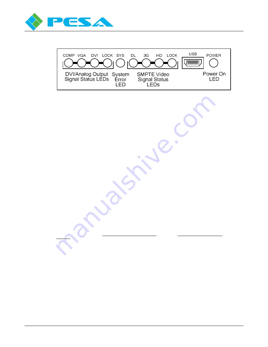
Figure 3-2 Front Panel Layout Diagram
•
Status LEDs - Refer to Paragraph 3.4.
•
USB – Vidblox TX modules communicate with a host PC over a standard USB bus using the
supplied cable. Attach the “mini” USB plug to this connector. It is not necessary to keep the
module attached to the host PC during normal operation.
•
POWER - When the Power LED is lit, it indicates the Vidblox module is connected to a source
of power.
Connect the power plug from the external power supply to the module power connector and connect the
power supply to a source of primary power.
When power is first applied to a receiver module, observe the front panel status LEDs for proper
operation as defined in Paragraph 3.4.
3.3
V
IDBLOX
A
UDIO
C
ONNECTIONS
The 3G-SL receiver module provides a 3.5mm jack for connecting unbalanced stereo (dual-channel)
analog audio output signals to a destination point. Audio is de-embedded from channels 1 and 2 of
digital audio group 1 on incoming SDI signal as shown in the chart below:
3.5mm Connector
Pin-out
Output Audio from Vidblox
De-Embedded Channel
Tip
Audio Channel 1
Left audio channel with normal stereo
source from computer sound card
Channel 1 of Group 1
Ring
Audio Channel 2
Right audio channel with normal stereo
source from computer sound card
Channel 2 of Group 1
Sleeve
Common Gnd
Содержание VIDBLOX 3G-NE RX
Страница 57: ......


