R
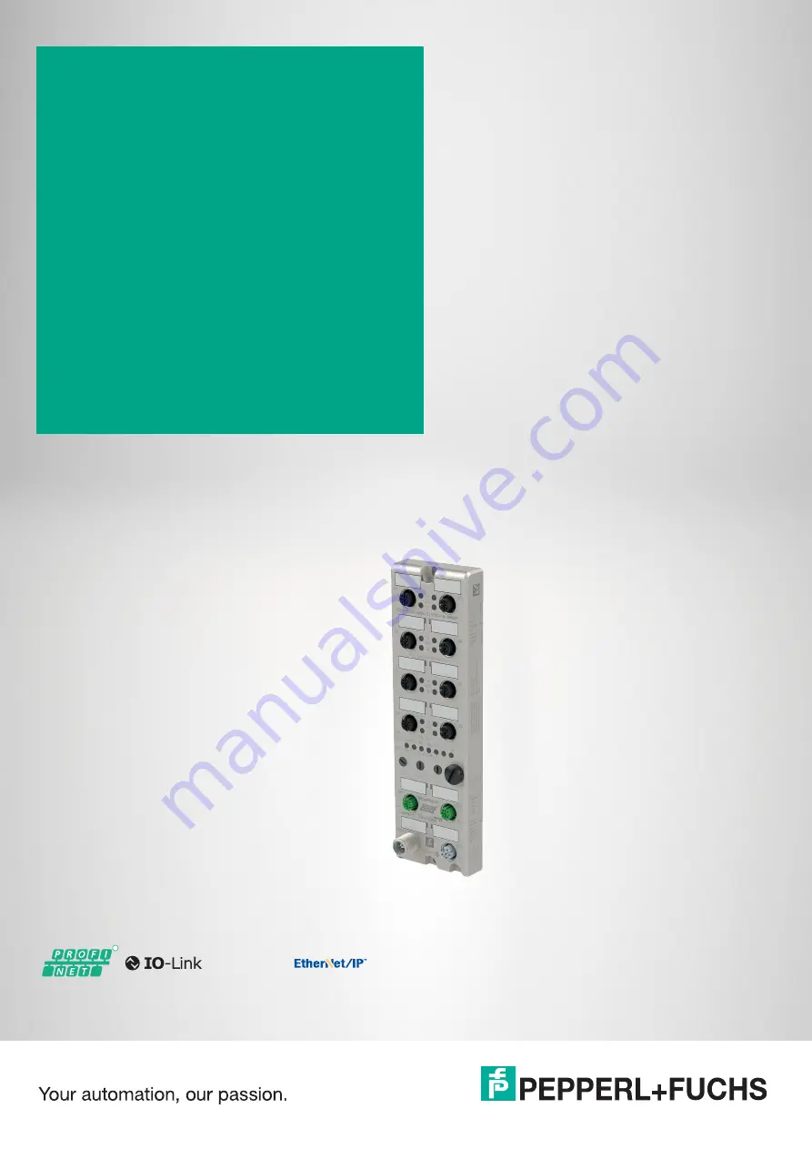
ICE1-8IOL-S2-G60L-V1D
Fieldbus Module with Multiprotocol Technology and I/O-Link
Manual
Страница 1: ...R ICE1 8IOL S2 G60L V1D Fieldbus Module with Multiprotocol Technology and I O Link Manual...
Страница 2: ...ion as well as the supplementary clause Expanded reservation of proprietor ship Worldwide Pepperl Fuchs Group Lilienthalstr 200 68307 Mannheim Germany Phone 49 621 776 0 E mail info de pepperl fuchs c...
Страница 3: ...5 2 3 Assigning the Device Name to a PROFINET IO Module 23 5 2 4 Configuring the IO Link Channels 26 5 2 5 Parameterization of the IO Link Channels 29 5 2 5 1 Fail Safe Configuration Outputs Only 29 5...
Страница 4: ...0 06 6 The Integrated Web Server 52 7 Troubleshooting 57 7 1 Diagnostics Indicator in the Integrated Web Server 57 7 2 Alarm Signals and Error Messages from Modules via PROFINET 57 7 3 Alarm Signals a...
Страница 5: ...conformity Attestation of conformity Certificates Control drawings Instruction manual Other documents 1 2 Manufacturer 1 3 Target Group Personnel Responsibility for planning assembly commissioning ope...
Страница 6: ...layed in descending order as fol lows Informative Symbols Action This symbol indicates a paragraph with instructions You are prompted to perform an action or a sequence of actions Danger This symbol i...
Страница 7: ...to this technology you can also use one module in different environments Using rotary coding switches in the lower area of the modules you can conveniently and easily set both the protocol and the add...
Страница 8: ...s to the modules in single write mode Single write mode does not activate the automatic parameter storage mechanism Force Mode In Force Mode the module ports can be temporarily configured as digital i...
Страница 9: ...hat is connected to two redundant PROFINET controllers This arrangement allows the additional controller to take over the IO data exchange connection if the connection to the primary controller fails...
Страница 10: ...de Green IO Link communication present Flashing green no IO Link device connected Off not configured for IO Link DIA LED B for each of X1 X8 B Red peripheral fault sensor and actuator overload or shor...
Страница 11: ...odule has determined that the assigned IP address already exists Flashing red the connection has timed out or been interrupted Off module is turned off or does not have an IP address Table 2 2 LED Fun...
Страница 12: ...t X01 X02 1 3 2 4 Caution Risk of destruction with external sensor supply The module infeed for the sensor supply US may only be provided over the specified power connection Power X03 X04 US 24 V GND_...
Страница 13: ...nel A IO Link data exchange 5 n c Not used Port Pin Signal Function IO Link Class B inputs out puts X5 X8 1 L IO Link sensor power supply 24 V 2 UAUX 24 V Channel B auxiliary voltage galvanically isol...
Страница 14: ...ower supply to the sensor and system via Us and auxiliary voltage via UAux for e g actuators Where the plant has a separate power supply concept for system current and load current this means the sens...
Страница 15: ...ICE1 8IOL S2 G60L V1D Product Description 2020 06 15 2 4 Dimensions Figure 2 6 ICE1 8IOL S2 G60L V1D 17 6 30 7 21 4 5 20 30 59 6 27 27 27 M12 x1 10x 27 11 5 16 5 190 3 191 8 200 M4...
Страница 16: ...dules use a short circuit to ground with an M4 thread This is marked with the symbol for grounding and the label XE Note Connect the module using a low impedance connection with the reference ground I...
Страница 17: ...switch X100 to the relevant switch position to set the protocol If you use EtherNet IP set the last octet of the IP address using the rotary switches X100 X10 X1 Figure 4 1 Rotary switch X100 Assignin...
Страница 18: ...e P Factory Settings A factory reset erases any changes you have made to settings etc and restores the factory settings The saved protocol selection is also reset To perform a factory reset set rotary...
Страница 19: ...menu Options Manage general station description files GSD The modules with a PROFINET interface are then available in the hardware catalog Figure 5 1 MAC IDs The modules have three assigned MAC IDs wh...
Страница 20: ...ype in the TIA portal based on the ICE1 8IOL S2 G60L V1D module 1 Install the GSDML file for the desired module in the TIA Portal Once the GSDML file for the PROFINET modules has been installed the mo...
Страница 21: ...5 3 Slot 1 is automatically occupied with the status control module which cannot be deleted The remaining subslots are configured as inactive by default and can be changed Figure 5 4 The following su...
Страница 22: ...rol System PROFINET IO devices are addressed in the PROFINET network via a unique device name This can be freely assigned by the user but must appear only once in the network 1 Select slot 0 in the mo...
Страница 23: ...ing the Device Name to a PROFINET IO Module Each module must have a device name so that each node in the PROFINET network can be assigned an IP address A node search displays all PROFINET devices that...
Страница 24: ...L S2 G60L V1D Commissioning for PROFINET 1 Connect the module to the PROFINET network 2 In Device View select the module Slot 0 3 Open the dialog Accessible devices via the main menu Online Accessible...
Страница 25: ...t of available nodes on the network you can change the device filter and refresh the list If the device still does not appear check your firewall settings 5 Assign the selected PROFINET device name to...
Страница 26: ...IO Link channels C Q or channel A pin 4 of the IO port in subslots 2 9 port 1 of the device corre sponds to subslot 2 etc port 8 of the device corresponds to subslot 9 can be defined as required The...
Страница 27: ...g dialog click Yes Figure 5 13 Creating an IO Link Channel Configuration 1 Different IO Link communication channels input channel output channel or input output channel are available in addition to th...
Страница 28: ...ink C Q channel channel A pin 4 Digital Input In this mode the channel works as a digital input The IO Link master does not attempt to independently establish communication with the connected IO Link...
Страница 29: ...h a value of 0 are transferred to the IO Link device Default setting Set High All bits of output data with a value of 1 are transferred to the IO Link device Inactive This mode should be selected when...
Страница 30: ...ller The PROFINET IO controller assigns the IO Link master port configuration Port and device configuration tool not yet supported An external IO Link port and IO Link device configuration tool assign...
Страница 31: ...alidation and backup test level Port cycle time Manufacturer identifier Device ID These parameters are GSD based and can be configured via the PROFINET engineering system Default IO Link Autostart Ove...
Страница 32: ...age locked the master will download the stored data onto the device where there are discrepancies The IO Link master can be replaced using the Backup function Restore master to device Parameter data c...
Страница 33: ...port mode is required for the Device ID option The device ID of the connected IOL device can be entered as a decimal value 0 65535 and is used for validating type compatibility depending on the Valida...
Страница 34: ...and the channel B bits are transferred alternately in ascending order for all ports Mapping for BMM1 BOM1 Mapping for BMM1 BOM2 BMM2 retrofit mapping In pin based bit mapping mode 2 BMM2 all ascending...
Страница 35: ...igh byte Mapping for BOM2 BMM1 Status control Bit 7 Bit 6 Bit 5 Bit 4 Bit 3 Bit 2 Bit 1 Bit 0 UINT16 High Bit X8A X7A X6A X5A X4A X3A X2A X1A UINT16 Low Bit X8B X7B X6B X5B X4B X3B X2B X1B Table 5 5 S...
Страница 36: ...Before the output can be switched on again it must be logically reset by the PLC Default Automatic Restart after Failure Digital Out Ch A Controlled by Port Submodule Use the output byte 1 bit 0 of t...
Страница 37: ...n also configure the separate auxiliary voltage UAux which is available on type B IO Link channels channel B pin 2 of ports 5 8 as an additional digital output Digital IO mode for Ch B area This enabl...
Страница 38: ...e an undamped sensor has an open switching output low signal The device input detects a low level and returns a 0 to the control unit NC normally closed In this case an undamped sensor has a closed sw...
Страница 39: ...by the control unit within the status control module A Surveillance Timeout can be parameterized for the outputs Surveillance Timeout Configuration area 5 2 7 Siemens IO Link Library IO Link Device P...
Страница 40: ...name To do so it uses the configured topology and the neighborhoods determined by the IO devices The Ethernet IO modules sup port the device replacement function without a removable medium programming...
Страница 41: ...Topology view 5 Use the mouse to drag a connection between the module and the PLC Figure 5 25 Note A network topology is configured based on the connections between PROFINET ports on the individual de...
Страница 42: ...of the system Supported I M Functions Module specific I M functions The module specific I M features 0 to 4 can be read or written via slot 0 The specified index is used for the mapping of data recor...
Страница 43: ...0xAFF1 Data object Length byte Access Default value description INSTALLATION_DATE 16 Read w rite 0x20 et seq empty The supported data format is a visi ble character string with a fixed length of 16 by...
Страница 44: ...PPORTED 2 Read 0x001E I M 1 4 supported Table 5 16 I M 0 slot 0 index 0xAFF0 Data object Length byte Access Default value description IOL_VERSION 1 Read 0x11 IO Link version 1 1 IOL_PROFILE_VERSION 1...
Страница 45: ...cal with the data type Hw_SubModule You spec ify the hardware identifier via the corresponding input parameter ID The I M index INDEX must also be transmitted The return parameters indicate the length...
Страница 46: ...ain a status or an error message 5 2 10 Prioritized Start Up Fast Start Up FSU The modules with Fast Start Up FSU support optimized system power up This ensures a quick restart after a power supply is...
Страница 47: ...ICE1 8IOL S2 G60L V1D Commissioning for PROFINET 2020 06 47 Figure 5 28 2 Select the module that you wish to reset to factory settings...
Страница 48: ...tes of output data for IO Link mas ters with S2 system redundancy When an IO Link master is selected from the GSD file the module is integrated automatically and cannot be changed The IO Link ports us...
Страница 49: ...d as the DO and the general deviceparameter Digital Out Channel A Controlled by is set to Status Control Module Other wise the control data is displayed in bit 0 of the corresponding subslot byte Inpu...
Страница 50: ...with MM2 and OM2 Input Bit 7 Bit 6 Bit 5 Bit 4 Bit 3 Bit 2 Bit 1 Bit 0 UINT16 High Bit DI X8A DI X7A DI X6A DI X5A DI X4A DI X3A DI X2A DI X1A UINT16 Low Bit DO X8B DO X7B DO X6B DO X5B DI X4B DI X3B...
Страница 51: ...mode depend on the configura tions of IO Link connections X1 X8 Data lengths between 1 33 bytes of input data and or 1 32 bytes of output data can be configured The data content can be taken from the...
Страница 52: ...ress of 0 0 0 0 You have to assign a free IP address that is different to the factory setting to the modules before using the web server Status Page Enter http in the address bar of your web browser f...
Страница 53: ...utomatically switches off To enable force mode enter user admin with the password private In offline mode you can configure the port mode via the wrench icon The following modes are available when doi...
Страница 54: ...s occur e g connection interruption controller on STOP internal module fault To visualize the Force Mode manipulation in the web server the behavior of the LEDs is dis played in the Device Overview ar...
Страница 55: ...ce information Revision Model number Serial number Week and year of production Network parameters IP Settings IP address readable and writable Subnet mask readable and writable Gateway address readabl...
Страница 56: ...r Administration Click on the User tab in the menu bar of the start window A new window opens with the user administration of the module Figure 6 4 On this page you can manage the users of the module...
Страница 57: ...n 7 2 Alarm Signals and Error Messages from Modules via PROFINET If the modules detect a fault state they trigger an alarm signal The modules support diagnostic alarms Diagnostic alarms are triggered...
Страница 58: ...hannelError contain the following values depending on the error that has occurred Cause OB call Diagnostics alarm short circuit overload wire break low voltage on an I O module OB82 Failure of a stati...
Страница 59: ...lobally An error message is generated if the voltage drops below approx 18 6 V or rises above 30 V The green US LED is switched off The error message has no effect on the outputs The following table s...
Страница 60: ...circuit channel B MI SCA Module information actuator short circuit channel A MI SCS Module information sensor short circuit MI LVA Module information low voltage auxiliary power supply MI LVS Module...
Страница 61: ...t with the Surveillance Time out parameter in the module configuration The value of this parameter can range from 0 to 255 ms the factory setting is 80 ms The filter is used to prevent premature error...
Страница 62: ...LVS Module information low voltage system sensor power supply CE X5B CE X8B Channel error channel B pin 2 of connections X1 to X8 IO Link Master Error IO Link C Q Error If an IO Link device is disconn...
Страница 63: ...bits can be set in the IO Link master status data This includes IOL DN Module information IO Link device notification IOL DW Module information IO Link device warning IOL DE Module information IO Link...
Страница 64: ...be set in the IO Link master status data Input Bit 7 Bit 6 Bit 5 Bit 4 Bit 3 Bit 2 Bit 1 Bit 0 Byte 5 0 0 0 0 0 IOL DN IOL DW IOL DE Byte 11 DW X8A DW X7A DW X6A DW X5A DW X4A DW X3A DW X2A DW X1A By...
Страница 65: ...Pepperl Fuchs Quality Download our latest policy here www pepperl fuchs com quality www pepperl fuchs com Pepperl Fuchs Subject to modifications Printed in Germany DOCT 6686...