


AIMA-FT5S
Product User Manual
Pacific Broadband Networks
18 July 2014
Page 28 of 62
5.8 Initial Setup
1. After calculating the correct RF drive level per channel for the channel plan to be used for BC
only or BC and NC. See formula
in section 6.1.1.
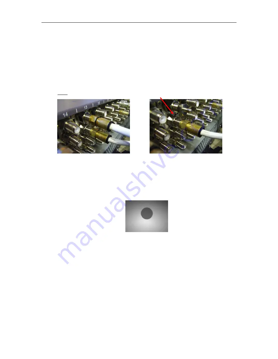
Confirm RF channel level only on the BC
RF input lead or BC and NC RF input leads and connect both to the chassis (pictured below).
Note:
if narrowcast is not in use install an “F” 75 Ω terminator to the NC RF input connection.
2. Before installing the FT5S, check the optical output ferrule tip with a fiberscope to ensure that
the connector is clean (pictured below). The cap on the optical output connector does not
prevent contamination from getting on to the optical connector, it prevents the laser from being
emitted when laser is on and no optical patch cord is installed.
3. Next install the FT5S unit into a slot where RF BC / NC input leads are connected and check
the optical output power with a cleaned optical patch cord and a calibrated optical power
meter. Record the optical output level. Connect a cleaned patch cord to the fiber output and to
the relevant optical distribution frame (ODF) panel.