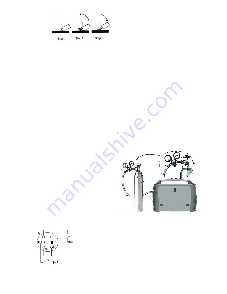
Where: Sw is the torch trigger
P is the potentiometer for controlling the current.
17.1 REMOTE CONTROL OF THE WELDING
CURRENT With remote connector 13 in Fig. 1, it
is possible to adjust the current near to the point
where the welding is being carried out. To do
so, it is necessary to create a connection with
potentiometer P, shown in figure 8. The value of
the potentiometer is not a critical factor: between
2.2kOhm and 10kOhm 1/2W can be used.
Turn the potentiometer and select the welding
current in a range between zero and the set
value.
18. CONNECTING THE OUTPUTS
Connection of the welding cables occurs via a
Dinse quick-connect system with appropriate
connectors.
19. CONNECTING THE GAS CYLINDER
AND THE GAS REGULATOR For TIG and
MIG welding only. For MMA welding, skip this
paragraph entirely.
Fig.9
1
2
3
4
5
6
At this stage, ignite the arc by moving the electrode
away from the workpiece a few millimetres (step
3 of fig.7). While maintaining the same distance
from the weld pool, whilst keeping the torch
trigger held down. Release the button to interrupt
the welding process.
16.POWER CONNECTOR
Before connecting the machine check the
tension, number of phases and the power
supply frequency. The admissible power supply
is indicated in the ‘Specific Techniques’ section
on page 5 of this manual and on the information
plate on the machine. Check that the earth
of the welder has been connected correctly.
Furthermore, make sure that the plug provided
with the equipment is compatible with the local
grid sockets. Make sure that the power supply
provides sufficient power for the machine to
function (tension ranges) The power supply
grid protection devices to be used are listed in
the ‘Specific techniques’ section of the present
manual. The machine is provided with a specific
power cable that does not usually require an
extension lead; in the event an extension lead is
required, use one of the same capacity [length?
sezione?] or higher than the machine in use,
according to the length of the cable. A 2.5 mm²
three-pole cable + earth, of the same size or
larger.
17. REMOTE CONNECTION Figure 8 shows
the connections of the remote connector (13 of
fig 1).
set welding current pass to the second level (I
2nd level) and vice versa. Prolonged pressure
on the torch trigger will halt the welding process.
2nd level current: When the 4Bi mode of the 2/4
settings is selected, the 2nd level current can be
set according to the percentage of the welding
current. start current: This sets the values of
the welding current settings required after the
ignition of the electric arc. start time: This sets
the time period of the current established in the
1. Connect the pressure regulator (2) to the
cylinder (3). Make sure the regulator is suitable
for the cylinder pressure. Attach the connector
nut (6) of the regulator (2) to the cylinder (3).
(Do not screw too tightly; excessive force could
damage the valve (1) of the cylinder (3).)
2. Connect the gas tube (4) to the regulator (2)
and secure with a cable tie (5).
3. Make sure that the gas tube is connected to
the welder correctly.
Содержание DP231C
Страница 1: ...ISSUE 2 User Manual DP231C...
Страница 2: ......
Страница 3: ......
Страница 4: ......


