


FL20-S Series
48
4.1 Main circuit wiring
4.1.1 Main circuit terminals
(1)
Main circuit terminals of 220V servo drive
Terminal
identification
Terminal
description
Functions
L1/R
,
L2/S
,
L3/T
Main circuit terminal
Used to connect three-phase AC 220V power.
L1 and L3 are used to connect to single-phase 220V power.
L1C
,
L2C
Control circuit terminal
Used to connect to two phases of three-phase power or
single-phase power.
B1/P
,
B2/B
,
B3
B2
,
B3
:
internal
braking resistor
terminal
Normally short-connect B2 and B3. Built-in braking
resistor is installed.
(M1 structure servo drive doesn’t have buit-in braking
resistor.)
B1/P
,
B2/B
:
external
braking
resistor
terminal
Normally not connected.
Remove the wire between B2 and B3 and connect an
external braking resistor between B1 and B2 if the internal
resistor is insufficient.
N+
,
N-
DC choke terminal
Normally short-connect N+ and N-. If a countermeasure
against power supply harmonic is needed connect a DC
choke between N+ and N- terminals.
U
,
V
,
W
Servo motor output
Used to connect to servo motor.
,
Ground terminal
Used to connect to the grounding.
(2)Main circuit terminals of 380V servo drive
Terminal
identification
Terminal description
Functions
R/L1
,
S/L2
,
T/L3
Main circuit terminal
Used to connect three-phase AC 380V power.
L1C
,
L2C
Forbidden being connected
Invalid
B1/P
,
B2/B
,
B3
B2
,
B3
:
internal braking
resistor terminal
Normally short B2 and B3. Internal braking resistor
is used.
(MM4 and above MM4 structure servo drive
doesn’t have buit-in braking resistor.)
B1/P
,
B2/B
:
external
braking resistor terminal
Normally not connected.
Remove the wire between B2 and B3 and connect an
external braking resistor between B1 and B2 if the
internal resistor is insufficient.
N+, N-, -
DC bus
Forbidden being connected to Grounding
U
,
V
,
W
Servo motor output
Used to connect to servo motor.
,
Ground terminal
Used to connect to the grounding.
Содержание FL20-S Series
Страница 1: ......
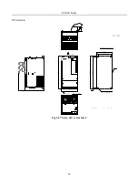
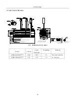
Страница 33: ...FL20 S Series 33 M3 structure Fig 3 1 5 Servo drive structure 3 ...
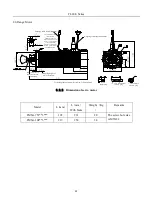
Страница 35: ...FL20 S Series 35 M4 structure Approx mass 10 365 kg Fig 3 1 7 Servo drive structure 5 ...
Страница 36: ...FL20 S Series 36 M5 structure Approx msaa 11 1Kg Fig 3 1 8 Servo drive structure 6 ...
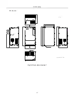
Страница 37: ...FL20 S Series 37 M6 structure Approx mass 17 4Kg Fig 3 1 9 Servo drive structure 7 ...
Страница 76: ...FL20 Series 76 1 2 No Name Function 1 DC 24V 2 DC 24V Plug No Name Function 1 DC 24V 2 DC 24V 3 None 1 2 3 ...
Страница 169: ...FL20 S Series 169 Fig 6 4 44FL20E Cam internal frameworkdiagram ...
Страница 347: ...FL20 S Series 347 ...


