


FL20-S Series
188
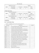
In the running process of torque mode, servo switches to speed mode when speed selection signal is
enabled, and run to target speed according to acceleration/deceleration time.
Torque
Curve
Internal
Speed 3
Setting
Torque
Internal Speed
Seleection 1
Internal Speed
Seleection 2
Speed
Curve
Setting
Torque
Internal Speed 1
Internal Speed
Selection 1
Internal Speed
Selection 2
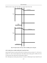
Fig 6.5.9 Speed mode and torque mode switching sequence diagram
(2)External analog speed and internal register torque switching mode, external analog speed and torque
switching mode show as figure 6.5.10, after servo is enabled, servo runs as torque mode when mode
switching signal is enabled; Servo runs as speed mode when mode switching signal is disabled.
In the running process of speed mode, servo switches to torque mode when mode selection signal is
enabled, and run to setting torque according to deceleration time.
In the running process of torque mode, servo switches to speed mode when mode selection signal is
Содержание FL20-S Series
Страница 1: ......
Страница 33: ...FL20 S Series 33 M3 structure Fig 3 1 5 Servo drive structure 3 ...
Страница 35: ...FL20 S Series 35 M4 structure Approx mass 10 365 kg Fig 3 1 7 Servo drive structure 5 ...
Страница 36: ...FL20 S Series 36 M5 structure Approx msaa 11 1Kg Fig 3 1 8 Servo drive structure 6 ...
Страница 37: ...FL20 S Series 37 M6 structure Approx mass 17 4Kg Fig 3 1 9 Servo drive structure 7 ...
Страница 76: ...FL20 Series 76 1 2 No Name Function 1 DC 24V 2 DC 24V Plug No Name Function 1 DC 24V 2 DC 24V 3 None 1 2 3 ...
Страница 169: ...FL20 S Series 169 Fig 6 4 44FL20E Cam internal frameworkdiagram ...
Страница 347: ...FL20 S Series 347 ...


