➂
Installation
19
Extending 6250 System Cables
This section describes options for extending 6250 system drive, encoder, and I/O cables. If
you wish to order longer cables, contact Compumotor's Customer Service Department at (800)
722-2282 or contact your local Compumotor Distributor or ATC.
6250-to-Encoder
Cables
Compumotor E Series encoders are supplied with a permanently attached 10-foot cable. The
maximum cable length between Compumotor encoders and the 6250 is 100 feet. If you wish
to lengthen the encoder cable yourself, use 24 AWG wire. Encoder cables should be shielded
with the shield connected to
SHLD
(pin 1 on the
ENCODER
connector).
You can also order encoders through Compumotor's Custom Products Group with the exact
cable length you want.
I/O Cables
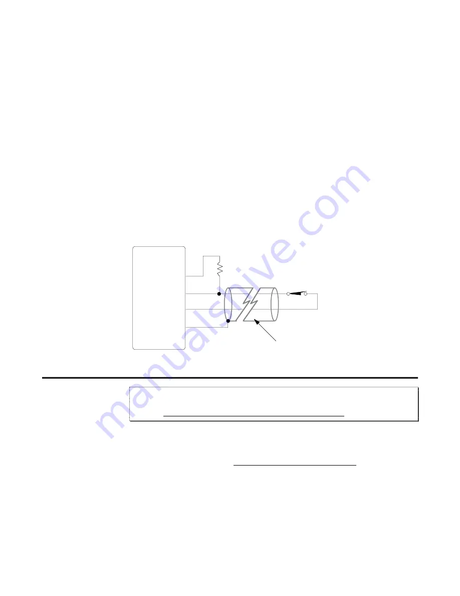
To avoid interference from external noise, you must shield all I/O cables, regardless of the
length. The maximum length of cables is determined by the environment in which the
equipment will be used. For cables longer than 50 feet or in electrically noisy environments,
you should follow the guidelines below (refer also to illustration below).
❏
22 AWG wire is the minimum recommended wire size.
❏
Use twisted pair shielded cables and connect the shield to the
SHLD
terminal on the 6250
connector. Leave the other end of the shield disconnected.
❏
Do not route these signals in the same conduit or wiring trays as high-voltage AC wiring.
❏
Limit and trigger inputs are internally pulled up to +5VDC and are TTL compatible. In
electrically noisy environments or when using long cable lengths, use an external pull-up
resistor with a value of 330
Ω
to 2.2K
Ω
between the input and +5V. The external resistor will
lower the input impedance and will make the input less susceptible to electrical noise.
Long Cable
Input Switch
470
Ω
6250
5V
Limit or Trigger
GND
Shield
➂
Installation Verification
WARNING
This installation verification section is intended to be executed with the drive not connected to
the 6250. Do not proceed until you are sure the drive is not connected.
➀
Return to the Test Procedure in Chapter 2 to test the drive/motor interface and the RS-232C
interface.
➁
Use the information in the following table to test the features appropriate to your application.
If you receive responses other than those expected, check your system wiring and refer to the
command description in the 6000 Series Software Reference Guide for assistance.


