14
6250 Servo Controller User Guide
Encoder Connections
The 6250 supports up to two incremental encoders. If you use encoders other than those
supplied by Compumotor, pay special attention to the following requirements:
❏
Use incremental encoders with two-phase quadrature output. An index or Z channel output is
optional. Differential outputs are recommended.
❏
It must be a 5V encoder to use the 6250's
+5V
output. Otherwise, it must be separately powered,
with TTL-compatible or open-collector outputs.
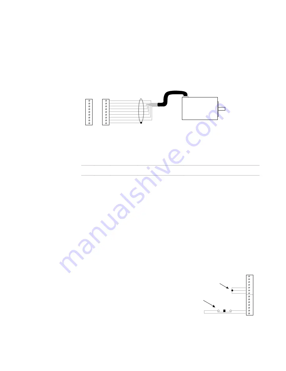
The illustration below shows the wiring techniques that you must use to connect encoders to
the 6250. Refer to Chapter 8 for the 6250's encoder input circuit drawing. If you are using the
BL or Dynaserv drives, refer to the connection illustrations earlier in the Motor Driver
Connections section.
Incremental
Encoder
Note for Using Single-Ended Encoders
If you are using a single-ended encoder leave the 6250's A-, B-, and Z- terminals not connected.
ENCODER 1
ENCODER 2
+5V
A+
A-
B+
B-
Z+
Z-
GND
SHLD
+5V
A+
A-
B+
B-
Z+
Z-
GND
SHLD
+5VDC
A C
A Channel -
B C
B Channel -
Z C
Z Channel -
Ground
Shield
Encoder
Connector Pin
Outs
Each axis has a 9-pin Phoenix connector for incremental encoder connections. The pin-out
description for the
ENCODER
connectors is provided below.
Pin
In/Out
Name
Compumotor E Series
Encoder Cable Colors
Description
9
OUT
+5V
Red
+5VDC output to power the encoder
8
IN
A C
Brown
A+ channel quadrature signal from encoder
7
IN
A Channel -
Brown/White
A- channel quadrature signal from encoder
6
IN
B C
Green
B+ channel quadrature signal from encoder
5
IN
B Channel -
Green/White
B- channel quadrature signal from encoder
4
IN
Z C
Orange
Z+ channel quadrature signal from encoder
3
IN
Z Channel -
Orange/White
Z- channel quadrature signal from encoder
2
-----
Ground
Black
Isolated logic ground
1
-----
Shield
Shield
Internally connected to chassis ground (earth)
Aux5V Output Connection
The 6250 pr5VDC output on the
AUX
,
ENCODER
, and
RP240
connectors. As much as
1.8A is available. 1.8A is sufficient power for the total load on all the I/O connectors. For
example, using two encoders (each drawing 250mA) and one RP240 (drawing 100mA), 1.2A
would be left for other purposes. The drawing below illustrates example connections for
powering the output pull-up.
Output and Input Pull-up Connections
OUT-P
(output pull-up) and
IN-P
(input
pull-up), located on the
AUX
connector,
provide power to the outputs and
inputs. The 6250 is shipped from the
factory with
OUT-P
and
IN-P
connected
to
+5V
to power the outputs and inputs
(see illustration at right).
+5V supplies power to OUT-P and IN-P.
This provides power to the output and input pull-ups.
(As an alternative, you can connect OUT-P and IN-P
to an external power source of up to 24V.)
If this switch is opened, the 6250's analog
command output signal is held to zero volts
(independent of the DSP and microprocessor).
AUX
Rx
Tx
GND
SHLD
+5V
OUT-P
IN-P
TRG-A
TRG-B
GND
OUT-A
OUT-B
GND
ENBL
Normally-closed
switch


