


BA_PH_3V_EN_07-22.docx
38
11.6
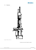
APA 2 - Saw Blade Guides
11.6.1
Structure and Components
The adjustment of the two saw blade guides is necessary
when starting up the machine as well as when changing
the bandsaw blade.
The structure is identical for the upper and lower saw
blade guide. The proven APA 2 saw blade guide consists of
the following components:
Pos. Description
Pos. Description
B
Support bolt
R
Back roller
2
H
Holder
S
Side rollers
K1
Tommy screw 1
V
Sealing plug
K2
Tommy screw 2
X
Rear clamp
L
Side bearing sleeve
Y
Front clamp
Figure 22: APA - Structure and components
11.6.2
Adjusting the Saw Blade Guides
To ensure proper functioning of the bandsaw, the two saw blade guides, each with two side rollers and a back
roller, must be correctly adjusted. The two side rollers serve to fix the saw blade laterally in the correct position.
The purpose of the back roller is to support the bandsaw blade during cutting against the force and movement
of the workpiece feed from behind.
Before adjustment, clean the guides thoroughly and remove dust, dirt and resin deposits. The procedure for
adjustment is identical for the upper and lower saw blade guides:
Figure 23: Adjusting the guides
•
Loosen the back roller with the tommy screw (
K2
) and move
it all the way back by pulling the sealing cap
8
on the back.
•
Adjust the two side rollers with the side bearing sleeves (
L
)
outwards so that a newly placed saw blade can run freely
between them.
•
Place the saw blade, tension and align it (see
•
Loosen the tommy screw (
K1
) and adjust the complete
guide on the support bolt (
B
) by moving it so that the front
edges of the side rollers are approx. 1 - 2 mm behind the
tooth base of the saw blade (see
•
Place the back roller against the back of the saw blade so
that it is not touched when the machine is idling.
•
Only the cutting pressure during machining may cause the
saw blade to touch the back roller.
•
Adjust side rollers so that they only lightly touch the saw
blade (se
Figure 24). Please take care that the saw blade
is not pushed to the side!
•
After adjustment, tighten tommy screws (
K1
) and (
K2
).
The bandsaw blade guide must not be set too high during machining.
There is a risk of injury from flying chips and a free-running saw blade!
2
With sealing cap (not visible in picture, as attached on the back)
S
L
V
B
R
K1
H
Y
X
K2
1-2 mm
K1
L
L
K2
Rear
(hidden view)
Содержание 3V
Страница 2: ...BA_PH_3V_EN_07 22 docx 2 Space for notes...
Страница 4: ...BA_PH_3V_EN_07 22 docx 4 Space for notes...


