BA_PH_3V_EN_07-22.docx
35
10.2
Frequent switching ON and OFF in succession
Avoid switching on and off several times in quick succession, as a bandsaw machine is not designed to be
switched on and off constantly. This may cause an overload, which will trip the fuses or the motor protection
device. In addition, on larger models with mechanical motor brakes and high flywheel mass, frequent switching
on and off can cause damage to the motor brake. The mechanical motor brakes of the bandsaws are designed
for a maximum of 10 braking cycles per hour.
Switching on and off several times in short intervals can cause damage to the machine
and/or the motor brake.
11
Settings and Operation
11.1
Basic Factory Setting
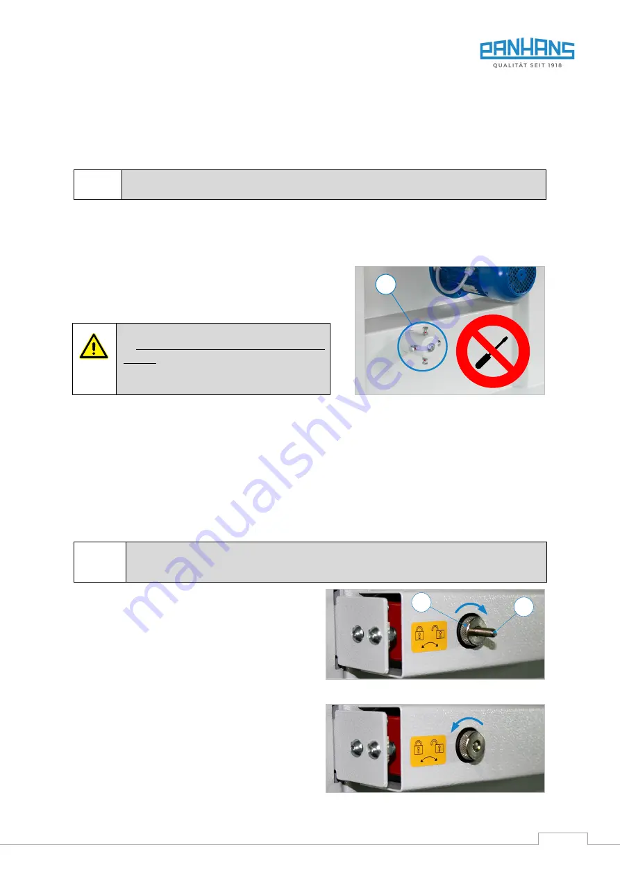
The machine is precisely adjusted and extensively tested be-
fore delivery. The bandsaw wheels are adjusted at the factory
using the adjustment points (
J
) provided on the machine, see
Figure on the right.
The adjusting screws at the adjustment points
(J) must not be manipulated under any circum-
stances. Otherwise the bandsaw wheels will
no longer be correctly aligned with each other.
This can cause the bandsaw blade to break.
Figure 16: Factory adjustment points
Adjustment of the adjustment points (
J
) is reserved exclusively for Hokubema Maschinenbau GmbH factory tech-
nicians! In case of doubt or problems with the machine, please contact our customer service department.
Note:
The adjustment screws are also protected against unauthorised opening with a red lacquer. If the screws
are nevertheless adjusted without authorisation, any guarantee for the repair of the resulting damage is invali-
dated in this respect.
11.2
Door Interlock with Safety Switches
To prevent unintentional door opening during operation and the associated dangers, the machine is equipped
with a safety switch on each of the two doors.
The doors of the bandsaw can only be opened if the safety switches have been unlocked with
the knurled screws (R) beforehand. To be able to restart the machine afterwards, the safety
switches must be locked again.
Unlock:
To open the door, the knurled screw (
R
) on the respec-
tive safety switch must be turned fully clockwise
↻
up
to the stop so that the threaded pin (
G
) protrudes com-
pletely from the housing of the switch.
→
The door is unlocked and can be opened.
Lock:
After changing the bandsaw blade, the door must be
closed and locked again. To do this, turn the knurled
screw (
R
) on the safety switch fully counter-clockwise
↺
until the grub screw (
G
) disappears completely into
the knurled nut again.
→
Only then can the machine be started again.
Figure 17: Safety switch - door unlocked
Figure 18: Safety switch - door locked
J
R
G
Содержание 3V
Страница 2: ...BA_PH_3V_EN_07 22 docx 2 Space for notes...
Страница 4: ...BA_PH_3V_EN_07 22 docx 4 Space for notes...


