BA_PH_3V_EN_07-22.docx
31
8.7
Electrical Connections
The connection must be carried out by an authorised electrician!
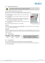
The circuit diagrams are located in the control cabinet.
Please observe the specified nominal voltage 400 VAC / 50 Hz (3 phases / N / PE)!
•
Ensure that the motor voltage (as indicated on the motor plate) matches
the mains voltage.
•
The supply cable is inserted through the cable gland at the bottom of the
control cabinet.
•
The connection to the mains (3 phases) is made at the terminal strip in
the terminal box or optionally in the control cabinet. The 3 phases must
be connected to the terminals
“
L1
”
,
“
L2
”
, and
“
L3
”
.
•
The protective earth wire (yellow/green) must be connected to the termi-
nal marked
“
PE
”
.
•
Then close the cable gland again so that it is dust-tight.
Figure 11: Control cabinet
Important:
Also check the correct running direction of the bandsaw blade. If the running direction is incorrect, two phases
in the control cabinet must be reversed.
Please note:
Only if the connection is carried out by an authorised electrician can a guarantee be given for the motor. In the
event of a complaint, the electrician must confirm in writing that he has connected the machine in accordance
with the regulations.
8.8
Backup Fuses
8.9
Supply Cable
Cu, 5-wire. The wire cross section must be determined on site by a qualified electrician.
The electrical wiring and connection must be carried out by a specialist in accordance with the applicable local
EVU, VDE and EN regulations.
Motor Power
3 kW
4 kW (Option)
The fault loop impedance and the suitability of
the overcurrent protection device must be
checked at the installation site of the machine .
400 V
16 A slow
20 A slow
Содержание 3V
Страница 2: ...BA_PH_3V_EN_07 22 docx 2 Space for notes...
Страница 4: ...BA_PH_3V_EN_07 22 docx 4 Space for notes...


