No. SX-DSV02472 -
45-
4-7 Absolute setup
4-7-1 Absolute encoder
When using the motor with absolute encoder or absolute/incremental common encoder, you can compose an absolute
system, which does not require to execute a homing operation at power-ON. For that, it is necessary to set Pr 0.15
(Absolute encoder setup) to “0”or “2” after connecting the battery for absolute encoder.
■ Parameters
Class
No.
At-
trib-
ute *1)
Title
Range
Unit
Function
0
15
C
Absolute
encoder setup
0–2
—
You can set up the using method of 17-bit absolute encoder.
*2)
0: Use as an absolute encoder.
1: Use as an incremental encoder.
2: Use as an absolute encoder, but ignore the multi-turn counter
over.
*1) For parameter attribute, refer to Section 9-1.
*2) During full-closed controlling, treated as an incremental encoder (setting value = 1) for internal control.
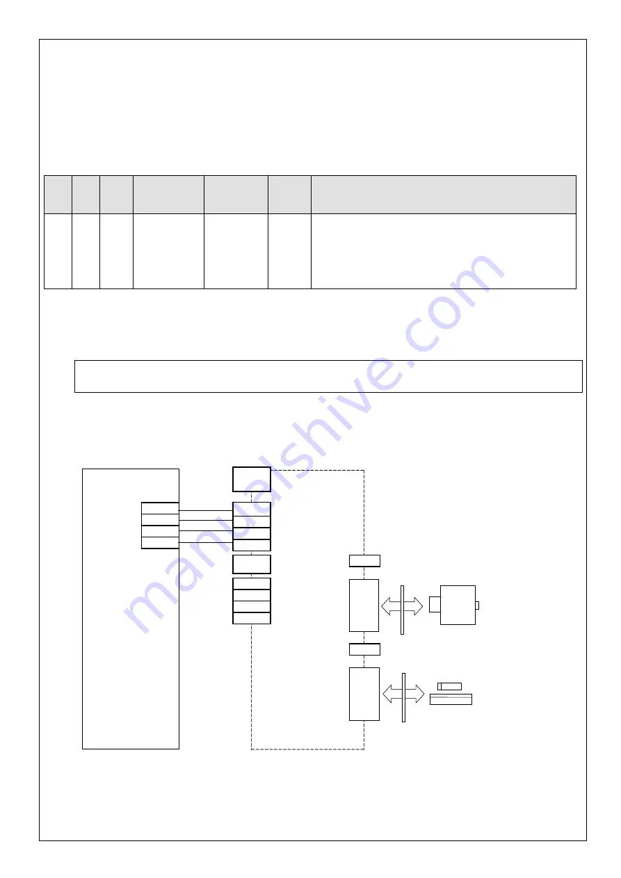
1) Structure of absolute system
Absolute system configuration using EtherCAT communication interface (example: with servo driver single-axis
connection)
In the EtherCAT communication response (driver
→
host controller), the absolute data is transferred to the host
controller as the current position data.
X6
Host controller
Servo driver
EtherCAT communication interface
Motor
encoder
1
2
Junction
Connector
ECAT IN
(X2A)
TX+
TX-
RX+
RX-
3
4
RX+
RX-
TX+
TX-
1
2
ECAT OUT
(X2B)
TX+
TX-
RX+
RX-
3
4
X5
Junction
Connector
Linear Scale Unit
Head
*1. Connect to either X4 or the junction connector between X6 and the encoder, when you connect the battery.
Do not connect to both.
Note: During replacing the battery, the control power input must be held ON. If not so, the absolute data will be lost.
R1.05
Motor Business Division, Appliances Company, Panasonic Corporation


