background image


EYFR03 User Manual 

109 of 110 

v1.6.0 

Chapter 12: Product Specifications 


20 January 2020 


Chapter 12:  Product Specifications 


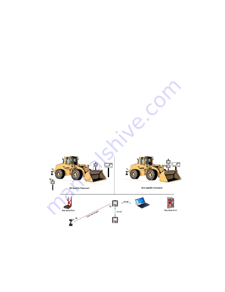
Qualifier Placement


• 

Mount the qualifier within 33ft of the tool during assembly. 

• 

Keep tool line of sight in view to the Qualifier.  Metal, stone, glass, plaster and other 
material will obstruct the wireless signal


• 

Avoid channels used by other 2.4Ghz tools.  Channel 1 is default in the qualifier


- Do a channel scan to choose the channel with the least interference. Page 42


         Channels 1, 6 and 11 are the most commonly used on 2.4Ghz hardware. 


• 

Avoid mounting the qualifier on vibrating surfaces


• 

Do not mount other equipment within 24-36” of the assembly qualifier


• 

Be aware of interference from other devices such as microwaves, wireless barcode 
readers, fluorescent lighting, power cables, garage door openers, walkie talkies, cordless 
phones, wireless security hardware and Bluetooth devises that can interrupt the 
wireless signal  


Содержание EYFR03

Страница 1: ...EYFR03 User Manual v1 6 0 20 January 2020 ...

Страница 2: ...History 17 Unit Status 18 Network Status 19 Tool Status 19 Chapter 3 Configuring the unit Introduction 22 Saving Configuration Changes 22 Entering letters 22 Main Menu 23 Tools 24 Parameters 27 Groups 31 Jobs 34 Network Settings 36 Qualifier Settings 37 NOK Options 40 Enter new Password 42 Reset Defaults 44 Channel Change 45 Events 45 Network Log 46 Chapter 4 Serial Communications Barcode 48 Seria...

Страница 3: ... Specific Objects 75 Assembly Object Connection Points 82 Backwards Compatibility Assembly Object Connection Points 89 Chapter 8 ToolsNet Introduction 94 Configuration Options 94 Chapter 9 PFCS Network Protocol Configuration Options 96 Protocol Settings 97 Parameter specific Machine ID s 97 Unsolicited Messages 99 Chapter 10 PROFINET Configuration Options 101 Data Format 102 Chapter 11 Data Manage...

Страница 4: ...EYFR03 User Manual 4 of 110 v1 6 0 Quick Start 20 January 2020 Quick Start ...

Страница 5: ...series of quick beeps and the display will show the loading progress Once loading is completed the unit should go to the Run screen If the unit stays on the loading screen with an error please contact support To use a tool with the qualifier you must first learn the tool to the qualifier To do so press the button below Menu Enter the password 1011 by default using the numeric keypad and press ENT ...

Страница 6: ...ool or vice versa Once the tool is learned the slot turns green to confirm successful then it will turn blue The unit will return to the Tools screen with the just learned tool now with a tool name of Tool 1 instead of No Tool Return to the menu by pressing ESC or the button below Exit Then press ENT to go to the Parameters screen To run a tool you must activate a parameter that uses the tool When...

Страница 7: ...p to 91 two way 4 Press the Ok button to accept the changes AccuPulse Tools in two way mode 91 will flash Orange on the rear LED when the parameter is selected If the tool is in sleep mode timed out from no operation and no display the tool will not communicate or flash orange Pulling the tool trigger will wake the tool and initiate communication then flash orange Tool sleep time can be changed in...

Страница 8: ...EYFR03 User Manual 8 of 110 v1 6 0 Chapter 1 Overview 20 January 2020 Chapter 1 Overview ...

Страница 9: ... to any cable or fitting Cautions Please use caution when handling this or any other electrical appliance This unit accepts an AC input voltage from 100 240 VAC Trying to operate this unit with a voltage outside that range may cause damage to the unit Avoid placing or storing this unit in a location where it may become wet or dust covered Do not place or mount this unit in an unstable area Droppin...

Страница 10: ... bar code reader The beeper provides an audio indication for any combination of accepts rejects and batch completions The beeper volume can be adjusted through the user interface See the Qualifier Settings section in the next chapter The power plug accepts 100 240 VAC at 50 60 Hz The right side of the EYFR03 A has a 24 pin discrete I O connector This connector is not available on the EYFR03 B mode...

Страница 11: ... up in the Tool Configuration screen which is described in the next chapter For tools with the appropriate firmware and setup the unit will use the enable disable or anti theft feature to only allow the tool to run when a parameter that uses it is active Parameters Parameters are the basic unit of operation for the EYFR03 A parameter contains a tool to run and some settings to use with it such as ...

Страница 12: ...re you have limited need to control tool operation but want to report rundowns from the tools Jobs Jobs are the top level of operation in the EYFR03 made up of multiple parameters or groups that must all run together in a sequence The EYFR03 supports 100 jobs with up to 30 steps each Unlike groups a job may have multiple parameters that use the same tool or even the same parameter or group multipl...

Страница 13: ... count for the tool will be shaded with a color indicating the status of the tightening Red A rejected tightening occurred Green An accepted tightening occurred that did not complete a batch Blue An accepted tightening occurred that completed a batch If the qualifier NOKs setting is set to Count this further indicates that no rejected tightenings were counted towards this batch Yellow An accepted ...

Страница 14: ...Status Indicator Shows the status of the tool for the parameter 6 Unit lock Indicates if the unit is locked and requires a password to access menu functions 7 Unit Radio Status Shows the status of the unit radio 8 Network Status Shows the status of the Ethernet and current number of connections 9 Soft Key 1 Function Shows the current function of soft key 1 10 Soft Key 2 Function Shows the current ...

Страница 15: ... 7 Unit lock Indicates if the unit is locked and requires a password to access menu functions 8 Unit Radio Status Shows the status of the unit radio 9 Network Status Shows the status of the Ethernet and current number of connections 10 Soft Key 1 Function Shows the current function of soft key 1 11 Soft Key 2 Function Shows the current function of soft key 2 12 Soft Key 3 Function Shows the curren...

Страница 16: ...r Repeated for each active parameter 5 Unit lock Indicates if the unit is locked and requires a password to access menu functions 6 Unit Radio Status Shows the status of the unit radio 7 Network Status Shows the status of the Ethernet and current number of connections 8 Soft Key 1 Function Shows the current function of soft key 1 9 Soft Key 2 Function Shows the current function of soft key 2 10 So...

Страница 17: ...uld be green with no number If the radio is not working correctly the indicator will be red with an error code Network Status Indicator The network status indicator shows the status of the Ethernet ports on the unit When the Ethernet is used the indicator will be green and show the number of currently active network connections If no Ethernet cable is plugged into either port the indicator will be...

Страница 18: ...s Figure 8 Unit Status screen Soft keys 1 I O Go to the I O Status screen see Chapter 5 Discrete I O 2 Network Go to the Network Status screen 3 Tool Go to the Tool Status screen 4 Exit ESC Returns to the Run screen The Unit Status screen shows some basic information about the current unit configuration that may be useful for diagnostics purposes The average signal strength is for all tools learne...

Страница 19: ... ports of the unit If no connection on a port is detected the unit will show Not connected If a connection is detected the baud rate and duplex of the connection will be listed Tool Status Figure 10 Tool Status Good Signal Figure 11 Tool Status Low Signal Figure 12 Tool Status Bad Signal Figure 13 Tool Status Last Signal Good Soft keys 1 Signal Show the signal strength of each tool 2 Address Show ...

Страница 20: ...Green The signal from this radio is strong and will work at best performance Yellow The signal from the radio is weaker than recommended for best performance The radio should work but may have slower or occasionally interrupted communication with the unit Red The signal from the radio is weaker than recommended for any use The radio may successfully transmit some results but will frequently have s...

Страница 21: ...EYFR03 User Manual 21 of 110 v1 6 0 Chapter 3 Configuring the unit 20 January 2020 Chapter 3 Configuring the unit ...

Страница 22: ...ing letters The unit has a special screen that allows using the numeric keypad to enter letters for fields that allow them such as a parameter name To get to this screen press ENT when the cursor is on a row with such a field Lowercase letters cannot be entered from the unit but can be entered through the PC software application The left side of this screen shows the letters associated with each n...

Страница 23: ... value Main Menu Figure 15 Main Menu The EYFR03 menu provides the entry point to configure and control the unit You must enter the box password before entering the menu from the Run screen If you cannot remember the password you may reset it to the factory default 1011 by entering the sequence 6853 48 on the Run screen Use the arrow keys to navigate to the desired entry and press ENT to go to the ...

Страница 24: ...hlight to the desired tool or typing the number of the desired tool When a learned tool is highlighted the soft keys are 1 Replace Learn a new tool in place of the current tool in this slot If you cancel out of the learn sequence the current tool will remain in the slot 2 Edit ENT Go to the Tool Configuration screen for the selected tool 3 Learn open Starts the learn sequence for the empty tool sl...

Страница 25: ...e radio address and the firmware version used by the radio to communicate with the qualifier The device has additional firmware to run the tool but no information about this firmware is reported Some features require a minimum radio version and tool firmware version Radio Version Features new in the version 4 33 Two way functions 3 19 Improved result buffering 3 17 Tool enable disable antitheft Th...

Страница 26: ...epted and rejected cycles This field cannot be edited If the tool is forgotten and relearned the cycle count will restart at 0 Last PM at This field stores the cycle count at which the tool last received preventative maintenance This field must be updated manually when the tool is serviced The count can be set to the current cycle count by selecting Set Now at the end of the row and pressing the E...

Страница 27: ... screen Soft keys 1 Select Select the currently highlighted parameter to run and return to the Run screen Only available for selectable parameters 2 Edit Edit the currently highlighted parameter 3 Copy Selects the currently highlighted parameter to be copied to another location 4 Exit ESC Returns to the Main Menu screen The Choose Parameter screen shows all the parameters in the unit in a 10x10 gr...

Страница 28: ...e The parameter name can be up to 25 numbers letters or decimal points The parameter name is shown on screen when running the parameter and reported to the network with tightenings performed in the parameter Tool This setting controls which tool is used by this parameter You must select a learned tool before a parameter can be used Parameters 1 16 always use the tool of the same number Parameter 1...

Страница 29: ...fore another tightening should be accepted Any additional tightenings performed within this time after an accepted tightening will be automatically considered a reject Time between batches Default 0 Range 0 to 9999 seconds This setting controls the minimum amount of time after a batch completion before another tightening should be accepted Any additional tightenings performed within this time afte...

Страница 30: ... by this setting the tool alerts the operator to a NOK fastening Variable speed control Default Variable Values Variable Single This setting controls if the tool run speed can be controlled by use of the trigger Cross thread reduction Default Off Range Off On 360 Reverse This setting controls if the tool uses its cross thread reduction behavior Retightening prevention Default 0 Range 0 to 3 0 seco...

Страница 31: ... Menu Groups Figure 28 Choose Group screen Soft keys 1 Select Select the currently highlighted group to run and return to the Run screen Only available for selectable groups 2 Edit Edit the currently highlighted group 3 Copy Selects the currently highlighted group to be copied to another location 4 Exit ESC Returns to the Main Menu screen The Choose Group screen shows all the groups in the unit in...

Страница 32: ...lock or restart the group when the group is completed When set to Yes the qualifier will not restart the group when all parameter batches are completed and will require a batch reset or parameter selection command to restart the group When set to No the qualifier will restart the group when it completes This setting is ignored when running the group as part of a job Batch beep on Default Group Val...

Страница 33: ...mmediately and may perform additional tightenings In this mode the Lock on done and Batch beep on settings are ignored Free run mode is intended for applications where the qualifier simply needs to report the tightenings from multiple tools but does not need to synchronize how much one tool runs compared to another Group Parameter Selection Figure 30 Group Parameter Select screen Soft keys 1 1 8 S...

Страница 34: ...n shows all the jobs in the unit in a 10x10 grid Jobs may be highlighted by using the arrow keys to move the highlight to the desired job or typing the number of the desired job Only the jobs with steps assigned will show their numbers on the grid A selectable job will have a black number A defined but not selectable job will be shown in red A job is defined when one or more parameters or groups a...

Страница 35: ... No the qualifier will restart the job when it completes Batch beep on Default Job Values Job Parameter This setting determines if the unit will sound the batch beep for each step in the job or only when the entire job is completed The UI will show the batch color for each individual parameter when it completes regardless of this setting Job Step Selection Figure 34 Job Step Select screen Soft key...

Страница 36: ...ps when running it as part of the job This column will be empty for group steps When a parameter is selected this column will be filled with the batch currently defined in the parameter itself Changing values in this column only affect the parameter while it is running in the job but does not change it in any other group or job or when the parameter runs on its own Network Settings Figure 35 Main ...

Страница 37: ...ally When set to yes the IP Address Subnet Mask and Gateway settings are ignored Qualifier Settings The Qualifier Settings screen contains the settings for the overall unit Figure 38 Main Menu Qualifier Settings Figure 39 Qualifier Settings Page 1 Figure 40 Qualifier Settings Page 2 Soft keys 1 Next Goes to the other page of the Qualifier Settings screen 2 Reset Defaults Goes to the Reset Defaults...

Страница 38: ... new channel The radio frequencies used by each channel can be found in Error Reference source not f ound Beep on reject Default Yes This setting determines if the qualifier will sound the beeper when a rejected tightening is received The reject sound is one long beep Beep on batch Default Yes This setting determines if the qualifier will sound the beeper when a batch is completed The batch sound ...

Страница 39: ...ning operation Partial seconds may be entered for this setting Batch completions are indicated by shading the screen blue or yellow behind the parameter that received the result to complete a batch Cycle timeout Default 2 seconds Range 0 to 10 seconds This setting controls how long the on screen indication of an accepted tightening that was not the last in a batch will be shown When set to 0 the i...

Страница 40: ...r will never automatically clear the VIN The VIN may still be cleared by other means such as a network command or discrete input When set to Yes the qualifier will clear the VIN when an operation completes regardless of if the operation is set to repeat When directly running a parameter the VIN will be cleared when a batch is completed When running a standard group the VIN will be cleared when all...

Страница 41: ... Values None Line CSV This setting determines the format used for serial printing of tightenings Bypass Verify Inputs Default no This setting determines if the Verify Tool and Verify Socket inputs are ignored See the Discrete I O section of the manual for more information about the inputs Startup Operation Default Last Values Last None This setting determines what operation will be run on unit sta...

Страница 42: ... password by typing the desired series of digits and pressing Save or ENT The new password will not be saved to permanent memory until saving from the qualifier settings screen If you decide not to change the password press Cancel or ESC You may completely remove the password from the unit by pressing Remove Removing the password will allow unrestricted access to all functions of the unit until a ...

Страница 43: ...Settings screen 4 RETURN ESC Returns to the Qualifier Settings screen without selecting a channel The new channel will not be saved to permanent memory until saving from the Qualifier Settings screen When a channel change is saved the unit will go to the Channel Change screen to guide you through updating all learned tools to use the new channel after saving from the Qualifier Settings screen ...

Страница 44: ...ou to restore the unit to the factory defaults You may select some or all parts of the configuration to reset Resetting some parts of the configuration may invalidate other parts that are not being reset Resetting May invalidate Tools Parameters Groups Jobs Parameters Groups Jobs Groups Jobs Jobs none Qualifier Settings Tools1 Network Settings none Tightenings none Events none I O Config none VIN ...

Страница 45: ... the unit to finish the channel change but will leave any skipped tools on the previous channel When you want to use the tools that were not updated they must be updated to the correct channel by pulling the battery and replacing it in the tool Make sure no other units are in learn mode when you do this or the tool may learn to the other unit instead The tool should reconnect to the unit on the ne...

Страница 46: ...ogs Figure 50 Logs Menu screen Network Figure 51 Network Log screen Function keys 1 No function 2 Previous Go to the previous page of more recent network events When on the first page this key will be blank 3 Next ENT Go to the next page of older network events When on the last page this key will be blank 4 Return ESC Returns to the Run Screen The Network Log screen shows the log of network events...

Страница 47: ...EYFR03 User Manual 47 of 110 v1 6 0 Chapter 4 20 January 2020 Chapter 4 Serial Communications ...

Страница 48: ...at of data within the bar code The data is grouped into sections separated by a percent symbol If the bar code data does not start and end with a percent symbol it will be treated as a VIN number The general structure for a command bar code is command data A VIN bar code is VIN number The remainder of this chapter lists the bar code commands provided by the unit Section headings are the command nu...

Страница 49: ...As such the same VIN could be provided as VIN1234567 5 Start Job This command instructs the unit to select a job Any other running parameter group or job will be stopped before starting the new job Data number of up to 3 digits specifying the job number to run 1 100 Example 05 32 This bar code would instruct the unit to start job number 32 6 Identifier part 2 This command sets the Identifier part ...

Страница 50: ... multiple parameters use command 30 Reset parameter batch count 11 Start Parameter This command instructs the unit to start a parameter Any other running parameter group or job will be stopped before starting the new parameter Data number of up to 3 digits specifying the parameter number to select 1 100 Example 11 73 This bar code would select parameter 73 12 Start Group This command instructs the...

Страница 51: ...at once use command 10 Reset batch count Serial Printer The EYFR03 provides serial printer output in two formats line and CSV The EYFR03 will print tightenings based on the format selected on the second page of the Unit Setup menu Additionally rejects may not be printed based on the Report to Network column of the NOKs setting table Both line and CSV formats contain the following fields in the sam...

Страница 52: ...YFR03 will store the scan in its Selector field but will not stop or change the running operation for a non matching scan When set to Stop the EYFR03 will discard the scan and blank both the Selector and VIN fields and will stop the running operation for a non matching scan When set to Ignore the EYFR03 will ignore any selector scans that do not match one of the VIN selections and act as if the sc...

Страница 53: ...u may select some or all the characters and are allowed to have gaps between matched characters if needed VIN Selection Matches Each entry in the VIN Selection Match list has a few values that you can set Match The string of characters that must be found in the scan Type The type of item to be selected for a matching selector One of Parameter Group or Job Number The item number to be selected for ...

Страница 54: ... selector length or does not match the VIN length if the selector is variable length against its selection list for a match and start the appropriate operation if a match is found Selector then VIN The EYFR03 will require a selector scan first followed by a VIN scan In this mode the VIN and selector lengths may be the same or different While the EYFR03 is waiting for the first scan it will ignore ...

Страница 55: ...EYFR03 User Manual 55 of 110 v1 6 0 Chapter 5 Discrete I O 20 January 2020 Chapter 5 Discrete I O ...

Страница 56: ...e I O Specifications Electrical Specifications Opto Isolated Inputs Item Value Unit min typ max Voltage 3 3 24 24 V DC Current 20 60 mA Impedance 1 5 KΩ Relay Outputs Item Value Unit Dry contact Voltage 24 V DC Current each 2 A Wet contact Voltage 24 V DC fixed Current each 2 A Current total 2 A fused Pinout Figure 52 I O Connector Pinout Number Type Wire color Function 1 Output White Relay 1 2 Ou...

Страница 57: ...to inputs and relay outputs may be assigned to a variety of functions as detailed in the following sections this table can only show the location of the relays and optos Common Points All inputs share a single common To use the box ground as the common connect Ground pin 24 to Opto common pin 23 on the I O connector All relays share a common point By default the relays are configured in a dry cont...

Страница 58: ...EYFR03 User Manual 58 of 110 v1 6 0 Chapter 5 Discrete I O 20 January 2020 ...

Страница 59: ... will be filled with yellow Inputs The inputs of the EYFR03 qualifier take 3 3 24VDC and have low current drain The discrete I O has a single common pin for all inputs and a signal pin for each input The inputs can be used to select an item to run or control the qualifier The selection inputs should not be used when the unit is being controlled by a network protocol as this will generally result i...

Страница 60: ...ntil the inputs correspond to another configured parameter the parameter is stopped or another parameter group or job is selected The number of required inputs depends on the maximum parameter that will be selected See the Binary selection of operations section below for more details about how to assign this field Select Group binary Inputs used up to 7 This group of inputs is used together to sel...

Страница 61: ...idual tools within a free run group allows running multiple tools simultaneously and independently while still retaining the ability to disable a single tool Batch Reset Inputs used 1 This input is used to reset the batch of the running operation If the current operation is a group the batch count for all parameters in the group will be reset If the current operation is a job the batch count for t...

Страница 62: ...N Inputs used 1 This input is used to bypass the requirement to have a VIN entered to perform an operation While this input is active the Require VIN to run qualifier setting is ignored If this input is deactivated during an operation while the Require VIN setting is set to Yes and no VIN is entered the unit will be suspended Verify Tool X Inputs used 1 per tool This input is used to verify an ind...

Страница 63: ...sed the more items you can select Number of Inputs Number of Selectable Items 1 1 2 3 3 7 4 15 5 31 6 63 7 100 The number of selectable items is also the maximum item number selectable for the number of inputs For example with 3 inputs you can only select parameters 1 7 not any combination of 7 parameters Outputs The outputs of the EYFR03 qualifier are 24VDC relays that can provide a total of 2A a...

Страница 64: ...r that will be indicated See the Binary representation of active operations section below for more details about how to assign this field Group Active binary Inputs used up to 7 This group of outputs is used together to indicate the number of the currently selected group The outputs are read together as a binary number to determine which group if any is selected This field will only have a value i...

Страница 65: ... output will behave as a latching output and will remain active until another tightening is performed by the tool or the parameter using the tool is stopped Tool X Cycle Reject Inputs used 1 per tool This output will be activated every time the tool performs a rejected tightening This output is a momentary output The duration this output will be active is determined by the Reject Timeout qualifier...

Страница 66: ...tting If the Batch Timeout is set to 0 this output will behave as a latching output and will remain active until another tightening is performed or another operation is started Binary representation of active operations The binary outputs Parameter Active binary Group Active binary and Job Active binary allow you to select the number of outputs to use The more outputs that are used the more items ...

Страница 67: ...EYFR03 User Manual 67 of 110 v1 6 0 Chapter 6 Atlas Copco Open Protocol 20 January 2020 Chapter 6 Atlas Copco Open Protocol ...

Страница 68: ...3 and jobs 10 11 and 12 are defined in the unit MID 0030 Job ID Upload request would return jobs 10 11 12 301 302 and 303 in the reply Similarly the MID 0034 Job Info subscription will give a message with job number 305 when group 5 is selected in the unit Configuration Options Figure 54 Main Menu Network Settings Figure 55 Network Settings Menu ACOP Figure 56 ACOP Settings Keep Alive Range 0 to 3...

Страница 69: ... will try again up to the specified number of retries If no response is received after all retries the ACOP connection is considered broken and will have to be re established This will terminate all subscriptions that were established on that connection regardless of which one did not receive a response Transmit Rejects Default Yes This setting determines if reject tightenings are sent to the ACOP...

Страница 70: ...re handled When set to No the following MID commands will return an error 0018 Parameter Select 0019 Parameter Batch Size 0020 Parameter Reset Batch 0038 Job Select 0039 Job Restart 0042 Tool Disable 0043 Tool Enable 0050 VIN Download 0082 Write Time 0127 Job Abort 0130 Job Off 0150 Multi ID Download 0156 Reset Latest Identifier 0157 Reset All Identifiers Protocol Mode Default 1 This setting deter...

Страница 71: ...upload request reply 0032 0033 1 3 Job data upload request reply 0034 0037 1 4 Job info subscribe acknowledge unsubscribe 0038 1 2 Select Job 0039 1 2 Job restart 0040 0041 1 4 Tool data upload request reply 0042 1 Disable tool 0043 1 Enable tool 0050 1 Vehicle ID Number download request 0051 0054 1 2 Vehicle ID Number subscribe acknowledge unsubscribe 0060 0063 1 4 Last tightening result data sub...

Страница 72: ...ACS tightening result Bold data 0108 Last PowerMACS tightening result data acknowledge 0109 Last PowerMACS tightening result data unsubscribe 0110 Display user text on compact 0111 Display user text on graph 0113 Flash green light on tool 0120 Job line control info subscribe 0121 Job line control started 0122 Job line control alert 1 0123 Job line control alert 2 0124 Job line control done 0125 Jo...

Страница 73: ...Open Protocol 20 January 2020 MID Revisions Command 0300 0301 Histogram upload request reply 0261 0264 Tool tag ID subscribe acknowledge unsubscribe 0400 0403 Automatic Manual mode subscribe acknowledge unsubscribe 0410 0411 AutoDisable settings request reply ...

Страница 74: ...EYFR03 User Manual 74 of 110 v1 6 0 Chapter 7 EtherNet IPTM 20 January 2020 Chapter 7 EtherNet IPTM ...

Страница 75: ... tools as specified for the product Instance Attributes ID Access Name Data Type Description of Attribute Semantics of Value 1 Set Name SHORT_STRING Name of the tool displayed on screen Maximum length is 25 characters 2 Get Last Modified DT Last time the tool attributes were modified 3 Get Type USINT Type of tool 0 none 1 3 reserved 4 battery 4 Set Last Calibration Date DT Date of last calibration...

Страница 76: ... Description of Service Class Instance 0x05 No Yes Reset Resets the tool slot to factory defaults No actual action is taken with the tool The tool is only forgotten by the qualifier 0x0E Yes Yes Get_Attribute_Single Returns the contents of the specified attribute 0x10 No Yes Set_Attribute_Single Modifies a single attribute ...

Страница 77: ... the device The maximum number of parameters as specified for the product Instance Attributes ID Access Name Data Type Description of Attribute Semantics of Value 1 Set Name SHORT_STRING Name of the parameter displayed on screen and reported in results Maximum length is 25 characters 2 Get Last Modified DT Last time the parameter attributes were modified 3 Set Tools UINT Instance numbers of tool u...

Страница 78: ...he device The maximum number of groups as specified for the product Instance Attributes ID Access Name Data Type Description of Attribute Semantics of Value 1 Set Name SHORT_STRING Name of the group Maximum length is 25 characters 2 Get Last Modified DT Last time the group attributes were modified 3 Get Number of Parameters USINT Number of parameters in Parameters array Maximum 16 4 Set Parameters...

Страница 79: ... Set Name SHORT_STRING Name of the tool displayed on screen Maximum length is 25 characters 2 Get Last Modified DT Last time the job attributes were modified 3 Get Number of Steps USINT Number of parameters in Parameters array 4 Set Steps ARRAY of STRUCT of Structure list containing the parameters to run for the job Maximum length is 30 Item number UINT Instance number of the item in the step Para...

Страница 80: ... 2 Beep on cycle 4 Set Beeper Volume USINT Volume level of the beeper Range 0 10 0 disables the beeper 5 Set Batch Timeout ITIME Duration to show the batch indicator on screen If 0 the indicator does not clear timeout Cannot be negative 6 Set Cycle Timeout ITIME Duration to show the cycle indicator on screen If 0 the indicator does not clear timeout Cannot be negative 7 Set Reject Timeout ITIME Du...

Страница 81: ...es ID Access Name Data Type Description of Attribute Semantics of Value 1 Set Require to start BOOL Indicates if a VIN is required to run an operation 2 Set Clear on complete BOOL Indicates if the VIN is automatically cleared when an operation completes 3 Set VIN SHORT_STRING Max Length 100 Services Service Code Available in Service Name Description of Service Class Instance 0x0E Yes Yes Get_Attri...

Страница 82: ... to run 0 Parameter 1 Group 2 Job Ignored if Item Number is 0 Batch Reset USINT When this value changes the batch counts of the currently running parameter or group is reset Suspend BOOL When set suspends the unit without stopping a running parameter group or job VIN SHORT_STRING Max length 100 Total size 6 106 bytes 161 Name Data Type Description Item Number UINT Instance number of items to run D...

Страница 83: ...Item Number is 0 Batch Reset USINT When this value changes the batch counts of the currently running parameter or group is reset Suspend BOOL When set suspends the unit without stopping a running parameter group or job Batch USINT Sets the batch size for the selected parameter If Item Type is not 0 Parameter this value is ignored If this value is 0 the parameter size stored in the EYFR03 will be u...

Страница 84: ...y batch size to use for each tool or 0 to make no modification Batch Reset WORD 16 bit word with each bit used to reset the batch of a tool when set bit 0 resets tool 1 bit 1 resets tool 2 etc Tool Suspend WORD 16 bit word with each bit used to suspend a tool bit 0 set suspends tool 1 bit 1 set suspends tool 2 etc Qualifier Suspend BOOL When set suspends the unit without stopping a running paramet...

Страница 85: ...last tightening was accepted as valid Count USINT Number of results performed in the current batch for the parameter Batch USINT Number of results required for a batch in the parameter Torque Unit ENGUNIT Unit used for torque fields Torque REAL Torque of the tightening just performed Min Torque REAL Minimum torque required for a tightening in the parameter Max Torque REAL Maximum torque required f...

Страница 86: ...s if the last tightening was accepted as valid Count USINT Number of results performed in the current batch for the parameter Batch USINT Number of results required for a batch in the parameter Total size 20 bytes 113 Name Data Type Description Tightening ID UDINT ID number of the last tightening Time DT Timestamp of the last tightening Tightening Status BOOL Indicates if the last tightening was a...

Страница 87: ...e When running an individual Parameter Multi Number 0 Complete will correspond to a batch completion When running a Group Multi Number non zero Multi Type 1 Complete will happen when the last parameter in the group to completes its batch When running a Job Multi Number non zero Multi Type 2 Complete will happen when the last step parameter or group in the job is completed Reserved Padding byte for...

Страница 88: ...the parameter Angle UDINT Angle of the tightening just performed Min Angle UDINT Minimum angle required for a tightening in the parameter Max Angle UDINT Maximum angle required for a tightening in the parameter VIN USINT 100 Reserved USINT Padding byte for devices requiring even connection point sizes Total size 192 bytes 131 Name Data Type Description Tightening ID UDINT ID number of the last tig...

Страница 89: ...ength arrays are represented as TYPE n where TYPE is the element type and n is the number of elements Output O T Connection Points Connection points in the 15x range correspond to the masks used with the EYFR01 which used only 150 as the output connection point These connection points are provided for backwards compatibility and are not recommended for new installations New data configurations sta...

Страница 90: ... provided to make the EYFR03 easier to drop into existing installations These connection points are not recommended for new installations 100 This connection point corresponds to the default mask of the EIP network card for the EYFR01 Name Data Type Description Parameter CHAR A H Tool Type CHAR 3 Type of the tool for the current parameter One of AIR Pneumatic air tools BAT Battery operated tool CL...

Страница 91: ...l Type for values Tool Type 6 CHAR 3 Type of tool in parameter 6 See Tool Type for values Tool Type 7 CHAR 3 Type of tool in parameter 7 See Tool Type for values Tool Type 8 CHAR 3 Type of tool in parameter 8 See Tool Type for values Total size 102 bytes 101 This connection point corresponds to the mask 1 of the EIP network card for the EYFR01 Name Data Type Description Parameter CHAR A H Tighteni...

Страница 92: ...EYFR03 User Manual 92 of 110 v1 6 0 Chapter 7 EtherNet IPTM 20 January 2020 Total size 4 bytes ...

Страница 93: ...EYFR03 User Manual 93 of 110 v1 6 0 Chapter 8 ToolsNet 20 January 2020 Chapter 8 ToolsNet ...

Страница 94: ...cols supported by the qualifier ToolsNet requires the controller to establish connections Since the qualifier will repeatedly make network requests to attempt to establish a network connection to the ToolsNet server you should only enable ToolsNet if you have a server set up in the network PIM server address Default 192 168 1 66 This setting controls the IP address the qualifier will use to establ...

Страница 95: ...number of retries If no response is received after all retries the ToolsNet connection is considered broken and will have to be re established Keep alive Default 30 seconds Range 0 to 3600 seconds This setting controls how often the qualifier will send a keep alive packet to the ToolsNet server if no other packets are being sent When set to 0 the qualifier does not send keep alive packets This val...

Страница 96: ...ation Options The PFCS network has several options that need to be configured to set up the device for use in the plant Besides the PFCS specific options listed below be sure to set the general network options such as device IP address under the General settings The main User Manual describes the process to set these options ...

Страница 97: ...mpt to establish a network connection to the PFCS server when enabled Enable Unsolicited Default no This setting determines if the qualifier will attempt to establish an unsolicited PFCS connection This setting is disabled by default because the qualifier will repeatedly make network requests to attempt to establish a network connection to the PFCS server when enabled Single Solicited Name Default...

Страница 98: ...fier will use an automatically assigned machine id on the unsolicited connection If this setting is set to no you must enter the desired machine id in the Unsolicited Name setting Unsolicited Name Default This setting determines the name the qualifier will use for unsolicited connections when not using an automatically assigned machine id on the unsolicited connection This setting is ignored if Un...

Страница 99: ...ingle Solicited Name setting is set to No the machine IDs for each parameter can be set from the IDs page Unsolicited Messages The EYFR03 allows the PFCS network to select parameters groups or jobs to be selected via the unsolicited messages The device specific data consists of a letter followed by a number of 1 3 digits The letter may be one of P G J or N When the letter is N the qualifier will s...

Страница 100: ...EYFR03 User Manual 100 of 110 v1 6 0 20 January 2020 Chapter 10 PROFINET ...

Страница 101: ... Figure 64 Main menu Network Setup Figure 65 Network Setup Menu PROFINET Figure 66 PROFINET Settings Enable PROFINET Default no This setting determines if PROFINET is enabled in the EYFR03 Please be aware that when enabling PROFINET the IP address in the EYFR03 will be erased and will either need to be reentered through the menu or set by a PROFINET configuration tool ...

Страница 102: ...NT ID number of the last tightening 22 1 Result Status USINT 0 OK 1 NOK 23 14 Tool Serial Number CHAR 14 Serial number of the tool that performed the last tightening 37 25 VIN CHAR 25 VIN of the last tightening Tool IO Module Output Offset Size Name Type Description 0 1 Job Number USINT Job number to run 1 1 Parameter Number USINT Parameter number to run Ignored if Job Number is not 0 255 means te...

Страница 103: ...e Speed Control USINT Controls if the tool run speed can be controlled by use of the trigger 0 Variable 1 Fixed 38 1 Temp Flush Detection Mode USINT Set to 1 for applications with light load before snug point Set to 7 for applications with heavy loads or varying joint rate before snug point range 1 7 39 1 Temp Torque Setting USINT Controls the torque setting of the tool range 0 40 40 1 Temp LED Li...

Страница 104: ...EYFR03 User Manual 104 of 110 v1 6 0 Chapter 10 Data Management 20 January 2020 Chapter 10 Data Management ...

Страница 105: ...ber This file contains all tightening results saved in the unit s memory in a CSV format Configuration The configuration file will be saved to the USB drive as conf eqc where the is the last four digits of the unit serial number This file contains all the configuration settings for the unit including tools parameters groups jobs qualifier and network settings and I O settings This file can be load...

Страница 106: ...mware Firmware files have the extension bec If a file is found the unit will validate the file before uploading it If a firmware file is uploaded the unit will reprogram itself with the new firmware and reboot Configuration Configuration files have the extension eqc If a file is found the unit must validate the file before uploading it These files can be created by downloading from a qualifier or ...

Страница 107: ...EYFR03 User Manual 107 of 110 v1 6 0 Chapter 11 Firmware Updates 20 January 2020 Chapter 11 Firmware Updates ...

Страница 108: ...should see the USB menu If the unit does not detect the drive contact support If the update was emailed to you you may also try another USB drive 5 To upload the firmware into the unit press the down arrow to highlight Upload USB file to device then press ENT This will take you to the USB Upload screen 6 When the unit changes to the upload screen it will search the root folder of the drive for the...

Страница 109: ... tools Channel 1 is default in the qualifier Do a channel scan to choose the channel with the least interference Page 42 Channels 1 6 and 11 are the most commonly used on 2 4Ghz hardware Avoid mounting the qualifier on vibrating surfaces Do not mount other equipment within 24 36 of the assembly qualifier Be aware of interference from other devices such as microwaves wireless barcode readers fluore...

Страница 110: ...mW 20 dBm EIRP Receiver sensitivity 100 dBm 1 packet error FCC Part 15 247 OUR XBEEPRO Industry Canada 4214A XBEEPRO Europe CE ETSI FCC Statement Channel Frequencies Channel Frequency GHz 1 2 410 2 2 415 3 2 420 4 2 425 5 2 430 6 2 435 7 2 440 8 2 445 9 2 450 10 2 455 11 2 460 12 2 465 Contains FCC ID OUR XBEE OUR XBEEPRO The enclosed device complies with Part 15 of the FCC Rules Operation is subj...

Отзывы: