– 211 –
Chapter 8 Connecting to External Devices — Connection function via <USB2.0> or <USB3.0> terminals
t
Download the USB driver from the website and install it into your computer. For installation procedure of the driver, refer to the installation manual on
the website.
For the latest information on the driver, visit the following website.
http://pro-av.panasonic.net/
t
The camera supports only USB 2.0. Ensure your computer supports USB 2.0.
t
When connecting the camera to a computer via USB, ensure that no other device is connected to the computer via USB.
t
When connecting the camera via USB, do not eject the P2 card.
t
When USB is connected, the P2 card access LED turns off when not accessed.
t
When the camera is operating in the USB device mode, no camera shooting, recording/playback operation or clip thumbnail operation is allowed.
t
When the camera is operating in the USB device mode, the P2 card remaining capacity and status are not displayed. Video and audio are not output
to the viewfinder, LCD monitor and <SDI OUT1> terminal or monitor output terminals (<SDI OUT2>, <HDMI OUT>, and <VIDEO OUT>).
USB storage mode
A hard disk drive or solid-state drive connectable to the <USB3.0> terminal (host) via USB 2.0 or USB 3.0 can be connected to store card data, view
thumbnails of saved clips, or write back to a P2 card.
Switching to the USB storage mode
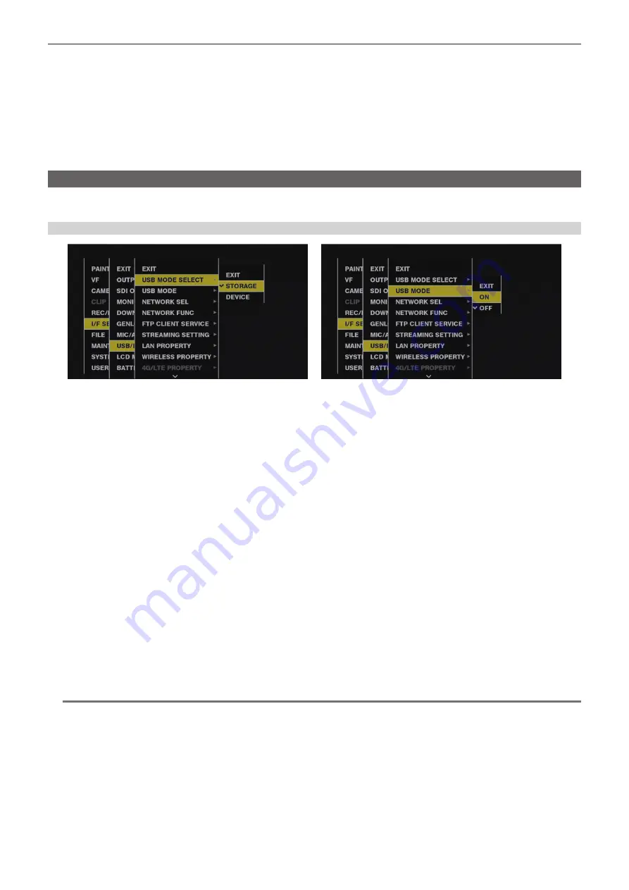
Fig. 1
Fig. 2
1
Set [STORAGE] in the main menu
→
[I/F SETUP]
→
[USB/LAN]
→
[USB MODE SELECT]. (Fig. 1)
For details, refer to “Setting menu basic operations” (page 147).
2
Set [ON] in the main menu
→
[I/F SETUP]
→
[USB/LAN]
→
[USB MODE]. (Fig. 2)
f
The camera enters the USB storage mode.
f
During USB storage mode, [USB STORAGE CONNECTED] is displayed at the center of the viewfinder screen and the <USB> lamp is illuminated.
If the hard disk drive is not connected properly, [USB STORAGE DISCONNECTED] is displayed and the <USB> lamp flashes.
f
[USB MODE] can be assigned to the <USER> buttons (<USER MAIN>/<USER1>/<USER2>), the <SHOT MARKER>, and <TEXT MEMO>
buttons in the main menu
→
[CAMERA]
→
[USER SW]; pressing these buttons switches between USB storage mode and normal storage mode.
However, if these buttons are pressed while a menu or thumbnail is open, the mode cannot be changed to USB device mode or normal mode.
For details, refer to “Assigning functions to <USER> buttons” (page 67).
3
Press the <THUMBNAIL> button.
f
The thumbnail screen is displayed.
f
Ensure that [USB] is displayed at the top right of the screen.
f
If a storage device is connected, the icon that indicates storage device status at the top right illuminates. However, a red mark indicates that the
device cannot be used.
For USB storage mode details, refer to “Connecting to external devices using the <USB3.0> terminal (host) (USB storage mode)” (page 138).
4
Exit the USB storage mode.
There are three ways to do so:
f
Turn the <POWER> switch of the camera to <OFF>.
f
With the thumbnail screen closed, set the main menu
→
[I/F SETUP]
→
[USB/LAN]
→
[USB MODE] to [OFF].
f
Press any one of the <USER> buttons (<USER MAIN>/<USER1>/<USER2>), <SHOT MARKER> button, or <TEXT MEMO> button to which [USB
MODE] is assigned. However, this is disabled when a menu or thumbnail is open.
@
@
NOTE
t
In USB storage mode, a P2 card can be played back. Camera video and external input cannot be recorded.
The clips written to the hard disk drive must be written back to the P2 card for playback.
t
A storage device cannot be connected to the <USB2.0> terminal (sub-host) (page 23).
t
While connecting a storage device, use a fully charged battery or an external DC power supply to avoid problems in copying or formatting operations.
t
For details on storage devices, refer to “Storage device types and available functions” (page 138).
Содержание AJ-PX5000G
Страница 9: ...Before using the camera read this chapter and check the accessories Chapter 1 Overview ...
Страница 219: ...This chapter describes how to use the camera by connecting to network Chapter 9 Network Connection ...
Страница 251: ...This chapter describes the dimensions specifications and connector signals Chapter 11 Specification ...


