29
“
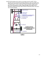
Horn
”
The
Headlight Section
has a single wire
dedicated for connection to a horn.
*
Most horns
ground through their mounting and only require a
power connection. This wire is:
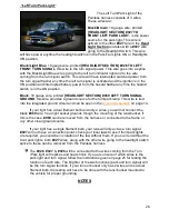
Black/Green
: 16 gauge wire, printed
[HEADLIGHT
SECTION] #924 HORN POWER
, this is a power wire
that comes from the fuse block mounted horn relay
which is ground activated by the horn button on the
steering column. This wire will only have power when
the horn button is pressed.
Route the
#924
wire to the horn. If you have to pass this wire through any
metal surfaces, you will find small grommets in the parts kit to protect the
wire.
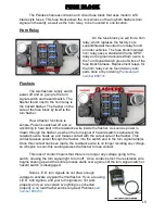
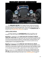
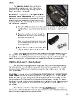
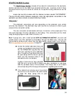
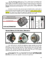
If you have a tab on the horn, locate the
terminal and connector, seen to the right,
provided in the parts kit.
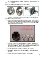
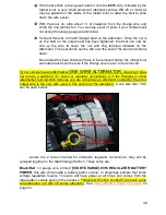
Ring terminals and heat shrink have been
provided for those with “screw” or “post &
nut” connections.
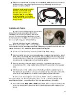
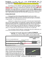
If your horn has a wire to connect to, then
a splice and heat shrink will be needed.
*
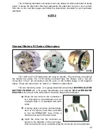
If your horn requires a ground wire, use a piece of scrap wire that was cut from
the any of the black
#969
ground wires on the driver side headlight or turn/park light
connections to connect the ground on the horn. Using a ring terminal from the parts kit,
attach the other end of the ground wire to a chassis ground source on the vehicle.
“Right Turn/Park Light” & “Right Headlamp”
The connections mentioned above all connect in the same manner as those on
the left/driver side. The only difference you will find is the Turn signal wire for the right
turn signal has a different color stripe that one used for the left turn signal. The right
Turn signal will be:
Black/ Blue
: 18 gauge wire, printed
[HEADLIGHT SECTION] #925 TO RIGHT FRONT
TURN SIGNAL
, this wire is the turn signal power. This wire goes into a splice with the
Black/ Blue wires going to the right turn indicator light and to the wire coming from the
turn signal switch. This wire will have interrupted switched power from the turn signal
flasher any time the left turn signal is activated and the ignition is in the ON position and
interrupted battery power from the hazard flasher any time the hazard switch is in the
ON position.
This concludes all of the connections in the
Headlight Section
of the engine
harness. Go back and inspect the harness layout and once satisfied it is free of moving
parts and sharp edges tighten any loose zip ties.

