31
Engine/Ignition Section
The
Engine Section
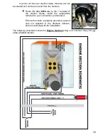
consists of five wires for connections to oil pressure and
coolant temperature sending units for the gauges, connections to the coil or ignition
system, and a connection for an electric choke on a carburetor. Locations of all of these
components will vary from vehicle to vehicle so no specific routing instructions can be
given.
All wires of the
Engine Section
will have ample length to account for the
numerous way components can be mounted inside an engine compartment. For
example: an Ignition box mounted on the inner fender will require more length of wire
than if power was going to a firewall mounted coil.
Coil / Ignition
Power to the coil / ignition system is supplied with a single wire coming from the
fuse block. The connection of this wire will vary depending on what ignition system,
factory or aftermarket, you use. The wire needed to supply a switched ignition power
source is:
Black/Pink
: 16 gauge wire, printed
[ENGINE SECTION] #920 TO COIL + (IGN.
POWER)
this wire comes from the 30 amp COIL fuse. This wire will have power
anytime the ignition switch is in the on and start positions. This wire will provide the Coil
/ ignition system with switched power in one of four ways:
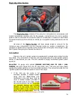
If the Coil you are using is not
internally resisted, a ballast resistor
along with the Black/Yellow wire
mentioned in the next step, must be
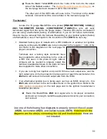
used. A ballast resistor, provided in
the kit and seen to the right, resists
the current going to the coil. If a coil is
not internally resisted and a ballast
resistor is not used, the coil will
overheat within a few minutes to the
point it will no longer work. See the
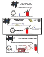
Ballast Resistor Connection
Diagram
on p.34.

