35
Engine Sending Units/Switches
The engine should have two gauge sending units: coolant temp and a oil
pressure. If you are using aftermarket mechanical gauges, then no connections will
need to be made. You can skip to the next connection, “Electric Choke” on page 37.
Sending units operate based on resistance to ground. Meaning the cooler the
engine or less oil pressure seen, the more ground (less resistance) these sending units
will provide to the wire connected to them. As the ground resistance strengthens as the
temps and/or pressure builds, less ground is applied to the gauge. As the ground signal
weakens, the needle on the gauge moves to read higher temps and/or higher oil
pressure. If you left these wires unconnected or have a bad ground between the
sending unit and engine/intake manifold, the gauges would peg to their highest reading.
“Coolant Temp”
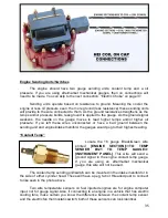
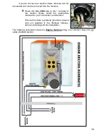
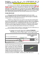
Locate the 18 gauge Black/Green wire
printed
[ENGINE
SECTION]<<TO
TEMP
SENDER
#921
TO
TEMP
GAUGE>>
[INSTRUMENT PANEL]
. This wire will send a
ground signal to the engine coolant temp gauge.
If you are using an aftermarket mechanical
gauge, this wire will not be used.
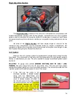
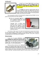
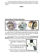
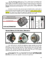
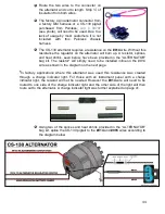
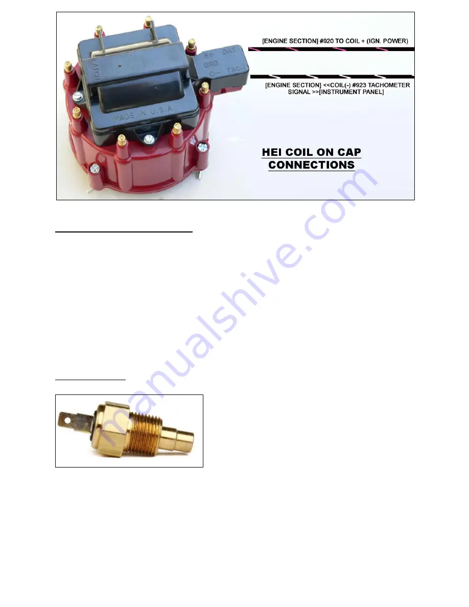
The coolant temp sending unit/switch can be mounted in the intake manifold or in
the side of either cylinder head. These will have a peg, tab or threaded post to connect
to like seen in the photo above.
Two wire temperature sensors on fuel injected engines are for engine computer
input, not for gauge signal. Also, if connecting to an engine in a vehicle that has electric
cooling fans, make certain you know the difference between the coolant temp sensor
and the electric fan thermostatic switch; both of these sensors can look identical.

