52
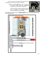
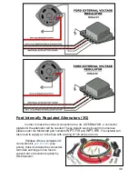
14 gauge wire(s) which run from the regulator to the field terminal(s) on the
alternator will need to be provided by the installer to finish the connections. These wires
are not in the Painless harness.
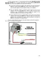
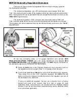
Connect the “FLD” terminal on the regulator to the “FLD” terminal on the
alternator.
“MIDI Fuse”
A large
in line MIDI fuse has been included in the “Alternator” bag kit. This inline
fuse will provide a fused link between the alternator and battery.
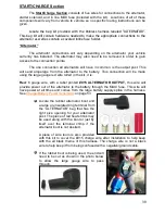
Find a suitable location to mount the supplied fuse holder using the 2
screws provided. A drill with a 3/32” or .100 bit will be required in order to drill
holes for the mounting screws. With the holes drilled, mount the fuse holder.
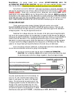
With the fuse holder now mounted locate the following two wires:
Black/Red
: 10 gauge wire, printed
[START/CHARGE] #916 TO BATTERY SOURCE
All power sources in this Painless harness originate from this wire. This wire provides
battery power to the fuse block, which in turn supplies battery power to the ignition
switch which provides switched power. During normal operation, this wire will have
constant battery power at all times.
Red
: 6 gauge wire, with a label printed
#915 ALTERNATOR OUTPUT,
this wire
provides power out of the alternator to the battery through the MIDI fuse. This wire will
have power at all times and comes from the large battery supply splice in the harness.
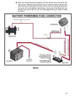
See
Battery Power Schematic
on the next page. The other end of this wire was
connected to the output post of the alternator.
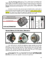
Route the
#916 and #915
wires to one side of the fuse holder and cut the
wires to length. Those using a MOPAR starter relay, please see page 56 before
cutting
#916
. DO NOT DISCARD THE CUT OFF PORTION OF
#915
.
The length of excess wire cut from the #915 wire will be used to connect the
other side of the
fuse to the “+” side of the vehicle’s battery or to the battery post
on the starter solenoid. DO NOT CONNECT THE #915 TO THE ACTUAL
BATTERY AT THIS TIME. If routed to the starter solenoid, this wire will NOT
replace the battery cable needed by the starter from the positive side of the
battery to the “BAT” or + post of the starter solenoid.
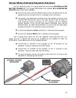
Connection to both sides of the fuse holder will be made using the large
ring terminals with the small #10 hole provided with the kit. You can use a
pair of pliers if your crimpers will not accept this large gauge wire/terminal.
The heat shrink supplied with this kit is intended to cover the crimped end
of each of these two ring terminals. A schematic showing these
connections can be found on the next page.

