


50
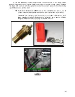
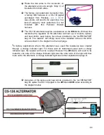
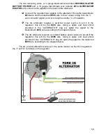
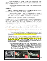
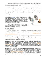
The two remaining wires, a 14 gauge black/red wire printed
#995 REGULATOR
BATTERY POWER
and a 16 gauge black/brown wire labeled
#914 ALTERNATOR
EXCITER
, will connect to the pigatils on the back of the alternator.
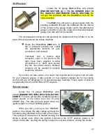
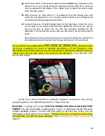
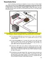
Connect the two alternator pigtails to the alternator. Route the black/brown
#914
wire and the black/red
#915
wire to the 2 wires coming from the 3
wire connector pigtail, and cut to length
and strip ¼” of insulation.
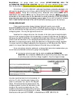
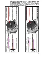
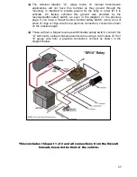
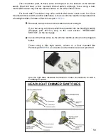
The 3G alternator requires a switched power source to pin
I
of the
regulator, this will be the
#914
wire.
Using a splice and heat shrink
provided in the “ALTERNATOR” bag kit, splice the pigtail to the
black/brown
#914
wire according to the diagram below.
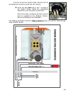
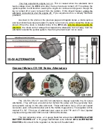
The 3G alternator requires a constant battery power source to pin
A
of the
regulator, this will be the
#995
wire.
Using a splice and heat shrink
provided in the “ALTERNATOR” bag kit, splice the pigtail to the black/red
#995
wire according to the diagram below.
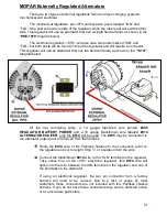
The 2G, and 4G alternators wire up in the same manner as the 3G in regards to
the “I” and “A” terminals on the regulator.


