9.0 WIRE CONNECTION INDEX
9.1
Wire Connection Index
In each section, connect the wire, as identified by its wire color, to the appropriate item in the CONNECT TO
column. Pay close attention to the Notes in this section, as identified by a small, raised number such as the
one at the end of this sentence.
Table 9-1 is divided into sections that correspond to the sections of your wire harness. (ACCESSORY
SECTION B+, DIMMER SWITCH SECTION, etc.). The index is divided vertically into six columns. COLOR,
GAUGE, NUMBER, CONNECT TO, ORIGIN, and SECTION OF ORIGIN.
The columns labeled ORIGIN and SECTION OF ORIGIN are for your reference ONLY. The items in these
columns tell you where each wire originates (ORIGIN) and from which section (SECTION OF ORIGIN) of the
harness.
The column labeled NO. contains a 900-series number that is used to identify various wires in the wiring
diagrams that are a part of these instructions.
Many (but not all) of the wire numbers occur TWICE in this index. That is because you will be connecting
BOTH ENDS of many of the particular wire segments. However, some wire segments are pre-connected at
one end. For instance, all wires originating from the fuse panel and certain other wires such as those
originating from the horn relay, the dimmer switch, and the instrument panel section. These pre-
connected wires are identified by an asterisk (*) in the ORIGIN column.
NOTES:
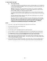
1. 2-color wires: 2
nd
color (stripe) may not be intense color. Observe two-color wires closely.
2.
This section consists of only one large (10 gauge) wire.
3.
From fuse panel to brake switch.
4.
This wire needs to go from the headlight switch to the instrument panel lights.
5.
This wire is power for the portion of the headlight switch that goes out to the headlights and front parking lights.
6.
This wire is power for the portion of the headlight switch that goes out to the instrument panel lights and the tail
lights. NOTE: This wire is only used if your headlight switch has two power input terminals.
7.
If a floor shifter is being used, utilize this extra length to route the 919 Yellow to the neutral safety switch on the
shifter or transmission and then to the starter solenoid. If not using a floor shifter, cut 919 Yellow to length needed
for starter solenoid and discard extra length.
8.
If a floor shifter is being used, utilize this extra length to route the 930 Orange to the gear select Indicator light on
the console. If not using a floor shifter, cut 930 Orange to length needed to reach the gear select indicator light.
19
Содержание 90542
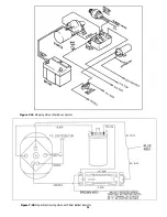
Страница 11: ...Figure 7 2A Mopar Ignition Start Run System Figure 7 2B Mopar Electronic Ignition with Dual Ballast Resistor 11...
Страница 22: ...22...
Страница 23: ...23...


