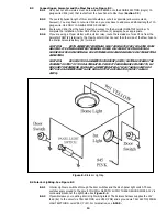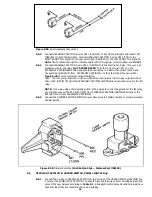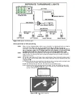
A perfectly and beautifully wired automobile will nevertheless have bugs and problems if everything is not
properly grounded. Do not go to the careful effort of installing a quality wire harness only to neglect proper
grounding.
Note: The Painless Wire Harness Kit includes no ground wire except the black wire from the two
headlamp connectors. You must supply ground wire (14-16 gauge) for all circuits.
6.3.1
Connect a Ground Strap or Cable (minimum of 2 gauge) from the Negative Battery terminal to the
engine block.
6.3.2
Connect a Ground Strap from the Engine to the chassis. DO NOT RELY UPON THE MOTOR
MOUNTS TO MAKE THIS CONNECTION.
6.3.3
Connect a Ground Strap from the Engine to the Body.
6.3.4
If you have a fiberglass body you should install a terminal block to ground all your Gauges and
Accessories. Ground the Terminal Block with at least a 12-gauge wire to the chassis.
6.4
Terminal Installation and Making Connections
Note: In the following steps you will be making the circuit connections. Before you start, you should
carefully read Sections 7.0 through 8.0, as appropriate, and continually refer to Section 9.0, DOUBLE-
CHECKING your routing and length calculations before cutting any wires and making connections. Give
special attention to Turn Signal and Ignition Switch connections. These can be somewhat confusing.
6.4.1
Have all needed tools and connectors handy.
6.4.2
Select the correct size terminal for the wire and stud application.
6.4.3
Determine the correct wire length and cut the wire. Remember to allow enough slack in the
harness and wires at places where movement could possibly occur, such as automobile body to
frame, frame to engine, etc. Double-check your calculations.
6.4.4
Strip insulation away from wire. Strip only enough necessary for the type of terminal lug you are
using.
Note: In the following step, make sure that the terminal is crimped with the proper die in the crimping
tool. An improper crimp will NOT make a good connection.
6.4.5
Crimp the terminal onto the wire.
CAUTION:
DO NOT OVER-CRIMP!
6.4.6
Connecting the harness throughout the groups is a redundant process. Make sure that each wire is
FIRST properly routed and THEN attach. DO NOT ATTACH FIRST THEN ROUTE AFTERWARD.
6.4.7
When all wires are attached, tighten the mounts and ties to secure harness permanently.
6.5
Testing The System
6.5.1
Use a small (10 amp or less) battery charger to power up the vehicle for circuit testing. If there is a
problem anywhere, the battery charger's low amperage and internal circuit breaker will provide
circuit protection.
CAUTION:
IF YOU HAVE NOT YET DISCONNECTED THE BATTERY FROM THE AUTOMOBILE,
DO SO NOW! DO NOT CONNECT THE BATTERY CHARGER WITH THE BATTERY CONNECTED.
Connect the battery charger's NEGATIVE output to the automobile chassis or engine block and its
POSITIVE output to the automobile's positive battery terminal.
6.5.2
INDIVIDUALLY turn on each light, ignition, wiper circuit, etc. and check for proper operation.
Note: The turn signals will not flash properly if you do not have both the front and rear bulbs installed
and connected.
6.5.3
When all circuits check out THEN attach the battery cable to the battery for vehicle operation.
8
7
MOPAR - SPECIFIC CIRCUIT CONNECTIONS
Содержание 90542
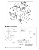
Страница 11: ...Figure 7 2A Mopar Ignition Start Run System Figure 7 2B Mopar Electronic Ignition with Dual Ballast Resistor 11...
Страница 22: ...22...
Страница 23: ...23...


