


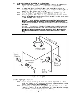

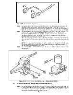


Figure 8.5A Dual Headlamp Connections
8.5.3 Connect HEADLIGHT SECTION A wires #927 (BLK/YLW) to ALL front Park Lights and wires# 927
(GRN/BLK) to both Marker Lights. Connect HEADLIGHT SECTION A wires #925 (TAN) to the
RIGHT FRONT Turn Signal(s). Connect wires #926 (GRN/RED) to the LEFT FRONT Turn Signal(s).
Note: Don't confuse Park Lights or Marker Lights with Turn Signals. For termination, see 8.10.3
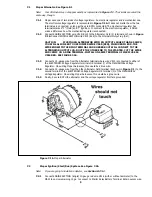
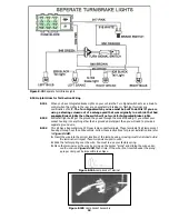
8.5.4 Connect HEADLIGHT SECTION A wire #901 (GRY/WHT) to the Electric Fan Relay. This wire is an
activation wire for the relay, NOT A POWER FEED. The other end of wire #901 is in the
ACCESSORY SECTION SWITCHES and should be connected to a electric fan switch in the dash.
Connect 906 (GRY/WHT) from ACCESSORY SECTION B+ to the other side of the fan switch.
Figure 8-4A shows a typical fan relay installation.
Note: The wire going to the fan in Figure 8-4B will be coming from the fan relay output terminal.
Wire #901
(GRY/WHT)
from the ACCESSORY SECTION SWITCHES is an activation wire for the fan
relay.
NOTE: If you are using a thermostatic switch in the engine to control the ground for the fan relay,
you will then connect the 901 (GRY/WHT) from ACCESSORY SECTION SWITCHES directly to the
906 (GRY/WHT) from ACCESSORY SECTION B+.
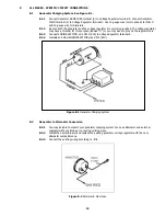
8.5.5 Connect the DIMMER SWITCH SECTION to your floor-mounted Dimmer Switch or column-mounted
Dimmer Switch.
Figure 8-5B Dimmer Switches (Push Button Style – Painless Part #80150)
8.6
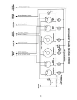
HEADLIGHT SECTION B, HAZARD SWITCH, PANEL LIGHT Wiring.
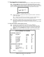
8.6.1 Connect the 5 wires of HEADLIGHT SECTION B, the 4 wires of the HAZARD SWITCH SECTION, the
3 wires of the PANEL LIGHT SECTION. You should trace out the wires of your existing harness and
connect the new harness according to Table 9-1. A headlight switch connector and terminals have
been provided; they are located in their own parts bag.
16
Содержание 90542
Страница 11: ...Figure 7 2A Mopar Ignition Start Run System Figure 7 2B Mopar Electronic Ignition with Dual Ballast Resistor 11...
Страница 22: ...22...
Страница 23: ...23...


