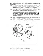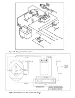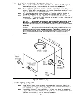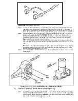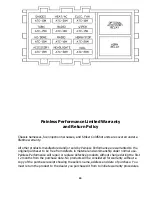
Figure 8-4A Typical Fan Relay Installation (Painless Part #30101)
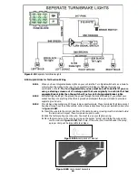
Figure 8-4B HEADLIGHT SECTION A Wiring
8.5 HEADLIGHT SECTION A. See Figure 8-4B.
8.5.1 Connect HEADLIGHT SECTION A wire #924 (GRN/RED) to the Horn's hot terminal. TURN SIGNAL
SECTION wire #953 (BLK) was connected in the Turn Signal Connector section of these
instructions. The Horn Relay is pre-wired into the Fuse Panel.
8.5.2 Connect HEADLIGHT SECTION A wires #908 (RED) to the GREEN and #909 (PPL/BLK) to the TAN
wires of BOTH Headlamp Connectors. For models with separate high beam head lamps, extra head
lamp connectors have been supplied. To make connections for separate high beam lamps, run a
jumper wire from the connection of wire #908 (RED) and the GREEN wire from the supplied
connector, to the GREEN wire of the high beam headlamp connector (see Figure 8.5 A). The TAN
wire of the high beam headlamp connector is not used. Connect the black wires of the Headlamp
Connectors to Chassis Ground. You should have enough wire to accomplish this. You have been
supplied with two small grommets (Figure 3-1) should you need to pass these wires through a
fender well. Don't forget to thread them onto the wires BEFORE you connect the wires.
15
Содержание 90542
Страница 11: ...Figure 7 2A Mopar Ignition Start Run System Figure 7 2B Mopar Electronic Ignition with Dual Ballast Resistor 11...
Страница 22: ...22...
Страница 23: ...23...


