List of Figures…………………………………………………………………………………………
i
List of Tables………………………………………………………………………………………….
4
List of Diagrams……………………………………………………………………………………..
4
1.0
Introduction…………………………………………………………………………………………..
4
2.0
About These Instructions………………………………………………………………………..
5
3.0
Contents Of The Painless Wire Harness Kit………………………………………………..
5
4.0
Tools Needed………………………………………………………………………………………….
6
5.0
Pre-Installation and General Harness Routing Guidelines…………………………….
6
6.0
Harness General Installation Instructions…………………………………………………..
7
6.1
Rough Installation………………………………………………………………………….
7
6.2
Harness Attachment……………………………………………………………………….
7
6.3
Grounding the Automobile……………………………………………………………..
8
6.4
Terminal Installation and Making Connections…………………………………..
8
6.5
Testing the System………………………………………………………………………..
8
7.0
Mopar - Specific Circuit Connections………………………………………………………….
9
7.1
Mopar Alternator……………………………………………………………………………
9
7.2
Mopar Ignition System……………………………………………………………………
9
7.3
Steering Column Wiring - Turn Signal Connections…………………………….
12
7.4
Steering Column Wiring - Ignition Switch Connections……………………….
12
8.0
All Makes - Specific Circuit Connections………………………………………………………
13
8.1
Generator Charging System…………………………………………………………….. 13
8.2
Generator to Alternator Conversion………………………………………………….. 13
8.3
Connecting to Ammeter and the Maxi-Fuse……………………………………….. 14
8.4
Interior Lighting……………………………………………………..………………………
14
8.5
Headlight Section "A"………………………………………………………………………. 15
8.6
Headlight Section "B"………………………………………………………………………. 16
8.7
Instrument Panel Wiring………………………………………………………………….. 16
8.8
Brake Light Switch…………………………………………………………………………… 16
8.9
Tail Section Wiring…………………………………………………………………………… 17
8.10 Helpful Hints for Tail Section Wiring………………………………………………….. 18
9.0
Wire Connection Index …………….………………………………………………………………… 19
LIST OF FIGURES
Figure 3.1
Painless Harness Kt………………………………………………………………………….. 5
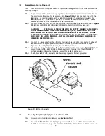
Figure 7.1A Mopar Alternator……………………………………………………………………………… 9
Figure 7.1B High Output Wire…………………………………………………………………………….. 10
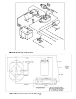
Figure 7.2A Mopar Ignition System……………………………………………………………………… 11
Figure 7.2B Mopar Electronic Ignition with Dual Ballast Resistor……………………………
11
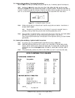
Figure 7.3 Turn Signal Terminal………………………………………………………………………… 12
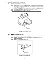
Figure 8.1
Generator Charging System………………………………………………………………. 13
Figure 8.2
Ammeter and Maxi-Fuse…………………………………………………………………… 13
Figure 8.3
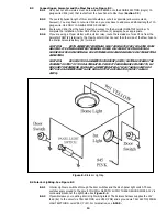
Interior Lighting……………………………………………………………………………….. 14
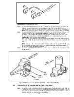
Figure 8.4A Typical Fan Relay Installation……………………………………………………………. 15
Figure 8.4B Headlight Section "A" Wiring…………………………………………………………….. 15
Figure 8.5A Dual Head Lamp Connections…………………………………………………………… 16
Figure 8.5B Dimmer Switches…………………………………………………………………………….. 16
Figure 8.7A Integrated Brake Light and ……………………………………..………………………. 17
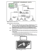
Figure 8.7b Separate Turn/Brake Lights ……………………………………………………………… 18
Figure 8.10A Lamp Socket Terminal……………………………………..……………………………… 18
Содержание 90542
Страница 11: ...Figure 7 2A Mopar Ignition Start Run System Figure 7 2B Mopar Electronic Ignition with Dual Ballast Resistor 11...
Страница 22: ...22...
Страница 23: ...23...


