Color
Ga. No. Connect to
Origin
Section of Origin
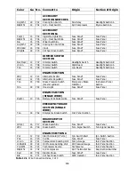
TURN SIGNAL
SECTION
Brn
14
751
Emer. Flasher Switch B+
Emer. Flasher Relay* Fuse Panel
Pur
14
752
Turn Signal Sw.Flasher B+ Turn Flasher Relay*
Fuse Panel
Blk
18
753
Horn Switch
Horn Relay*
Fuse Panel
Grn
14
748
Turn Signal Switch
Rt.Rear Turn Signal
Tail Section
Ylw
14
749
Turn Signal Switch
Lt.Rear Turn Signal
Tail Section
Blu
18
725
Turn Signal Switch
Rt.Front Turn Signal
Headlight Section A
Wht
16
718
Turn Signal Switch
Brake Switch
Engine Section A
Lt.Blu
18
726
Turn Signal Switch
Lt.Front Turn Signal
Headlight Section A
RADIO SECTION
Red/Blk
18
741
Radio B+ Switched
Fuse Panel*
Fuse Panel
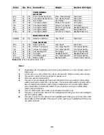
TAIL SECTION
Wht
18
745
Dome Lights B+
Fuse Panel*
Fuse Panel
Grn
14
748
Rt.Rear Turn Signal
Turn Signal Switch
Turn Signal Section
Ylw
14
749
Lt.Rear Turn Signal
Turn Signal Switch
Turn Signal Section
Pnk
18
739
Fuel Sending Unit
Fuel Gauge
Instr. Panel Section
Brn
14
729
Tail Lights
Headlight Switch
Headlight Section B
Orn
18
750
Third Brake Light
Turn Signal Switch*
Turn Signal Section
Lt.Grn(1) 18
756
Backup Lights
Backup Switch
Cruise Control Section
Table 12.1 Wire Connection Index, 3 of 3
Notes:
1.
Depending upon the particular wire harness you purchased, you may not have some of
these wires.
2.
2-color wires: 2
nd
color (stripe) may not be intense color. Observe 2-color wires closely.
3.
This section consists of only one large (10-gauge) wire.
4.
From fuse panel to brake switch.
5.
This wire is cut and spade lugs have been installed so that your existing neutral safety
switch circuit can be wired into your harness. The neutral safety switch is located at the
base of Jeep steering columns and in Mopar transmissions. Do not attempt to defeat
your automobile’s neutral safety switch. If your Jeep does not have a neutral safety
switch, please install one.
6.
This is a short length of wire that is not connected on either end.
7.
This wire is power for the portion of the headlight switch that goes out to the headlights
and front parking lights.
8.
This wire is power for the portion of the headlight switch that goes out to the instrument
panel lights and the taillights. This wire will not be used if your headlight switch has only
one power terminal.
33
Содержание 10106
Страница 29: ...Figure 8 8 Ford Ignition Diagram Duraspark II Systems Figure 8 11 Ford Switch Connectors 24...
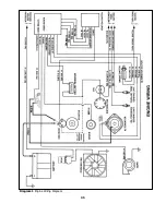
Страница 40: ...Diagram 1 Engine Wiring Diagram 35...
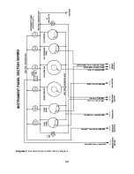
Страница 41: ...Diagram 2 Instrument Panel Section Wiring Diagram 35...
Страница 42: ...Diagram 3 Integrated Brake Lights Separate Turn Brake Lights 36...
Страница 44: ......

