7.0
GENERAL ELECTRICAL SYSTEMS – ALL JEEPS
7.1
Generator Charging System. Use Paragraph 8.1.1.
7.2
Generator to Alternator Conversion. Use Paragraph 8.1.2.
7.3
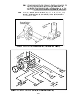
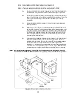
Connecting an Ammeter and the Midi Fuse. See Figure 7.1.
Figure 7.1 Ammeter & Midi Fuse
7.3.1
The Ammeter must be inserted IN SERIES onto the ENGINE SECTION (single
10-gauge red wire #716) that routes from the Fuse Panel to the Starter Solenoid
(Starter Relay if you have a Ford or Mopar starter system).
7.3.2
The overall physical length of this circuit should be as short as possible (allow
some slack, however). You may have to cut wire #716 and you may have to add
some additional length of 10-gauge wire. USE ONLY 10-GAUGE WIRE.
7.3.3
Route wire #716 (from the Fuse Panel) and connect to the Ammeter NEGATIVE
terminal. To complete the installation, follow ONE of the next three paragraphs,
as appropriate.
7.3.4
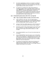
If you are using a Delco Starter, route the remainder of wire #716 from the
Ammeter POSITIVE terminal to the Starter Solenoid Battery (B+) terminal. This
is the terminal to which the battery cable is connected. Splice the MIDI-Fuse
(Figure 8.3) onto the end of wire #716 and connect to the Starter Solenoid
Battery (B+) terminal.
7.3.5
If you are using a Ford starter relay, route the remainder of wire #716 from the
Ammeter POSITIVE terminal to the Starter Relay Battery (B+) terminal. This is
the terminal to which the battery cable is connected. Splice the MIDI-Fuse
(Figure 8.3) onto the end of wire #716 and connect to the Starter Relay Battery
(B+) terminal.
7.3.6
If you are using a Mopar starter relay, route the remainder of wire #716 from
the Ammeter POSITIVE terminal to the Starter Relay Battery (B+) terminal, and
from this terminal to the Starter Solenoid Battery (B+) terminal. This is the
terminal to which the battery cable is connected. Splice the MIDI-Fuse (Figure
8.3) onto the end of wire #716 and connect to the Starter Solenoid Battery (B+)
terminal.
8
Содержание 10106
Страница 29: ...Figure 8 8 Ford Ignition Diagram Duraspark II Systems Figure 8 11 Ford Switch Connectors 24...
Страница 40: ...Diagram 1 Engine Wiring Diagram 35...
Страница 41: ...Diagram 2 Instrument Panel Section Wiring Diagram 35...
Страница 42: ...Diagram 3 Integrated Brake Lights Separate Turn Brake Lights 36...
Страница 44: ......


