F.
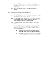
The Ignition Coil NEGATIVE (-) terminal is connected to the Distributor.
Also connect ENGINE SECTION A wire #723 (pur/wht) to the Ignition
Coil NEGATIVE (-) terminal. This is the tachometer source. If you are not
using a tachometer, insulate and stow wire #723.
G.
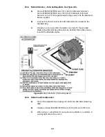
A 14-gauge wire connected from the Starter Solenoid Ignition (l)
terminal to the ignition coil side of the Ballast Resistor is optional. This
wire (in Figure 8.4) serves as a Ballast Resistor BYPASS during engine
starting. However, if the starter solenoid shorts out, which is not
unusual, the engine will stop running and will not restart as long as this
wire is connected. You may therefore choose to omit it. If you are not
using a Ballast Resistor, leave the Starter Solenoid Ignition (l) terminal
unconnected and do not install the bypass wire.
8.2.5
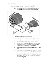
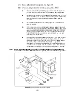
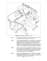
Prestolite BID Ignition System (1975-1977). See Figure 8.6
Note: If you are going to install an ammeter, see Section 7.3 first.
A.
Locate the Electronic Control Unit. It may not appear exactly as
represented. All wires connected to this unit MUST REMAIN CONNECTED
IN THEIR ORIGINAL CONFIGURATION. You may replace them, one at a
time, and incorporate them into the new harness, if you wish.
B.
Route and connect the provided 6 gauge red wire from the alternator to
the MIDI fuse. Ring terminals from the “Alternator” bag are provided.
C.
Connect the cut off end of the provided 6 gauge red wire from the other
side of the MIDI fuse to the Starter Relay Battery terminal. This is the
same lug to which the large red cable from the battery is normally
connected.
D.
Connect ENGINE SECTION A wire #719 (pur) to the Starter Relay Start
(S) terminal.
E.
Connect ENGINE SECTION A wire #720 (pnk) to one end of the Ballast
Resistor. Connect the other end of the Ballast Resistor (or resistive wire)
to the Ignition Coil POSITIVE (+) terminal with 14-gauge wire (you may
have enough pink wire left over to accomplish this). If you are using a
Ballast Resistor, mount it away from other wiring or hoses. The Ballast
Resistor gets very hot during operation.
F.
A 14-gauge wire connected from the Starter Relay (l) terminal to the
ignition coil side of the Ballast Resistor serves as a Ballast Resistor
BYPASS during engine starting. If you are not using a Ballast Resistor (or
resistive wire), this jumper is not necessary.
21
Содержание 10106
Страница 29: ...Figure 8 8 Ford Ignition Diagram Duraspark II Systems Figure 8 11 Ford Switch Connectors 24...
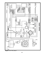
Страница 40: ...Diagram 1 Engine Wiring Diagram 35...
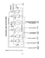
Страница 41: ...Diagram 2 Instrument Panel Section Wiring Diagram 35...
Страница 42: ...Diagram 3 Integrated Brake Lights Separate Turn Brake Lights 36...
Страница 44: ......


