9.0
CHARGING AND IGNITION SYSTEMS – JEEP WITH GM ENGINES
INSTALLED
Note: Your Alternator may not appear exactly as represented in the Figures. The
circuits are wired the same way, though.
9.1
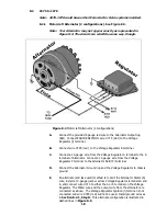
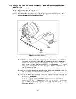
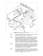
Delco Alternator (before 1969) – External Regulator. See Figure 9.1.
9.1.1
Connect ENGINE SECTION wire #795 (red) to Voltage Regulator terminal 3.
9.1.2
Connect ENGINE SECTION wire #714 (wht) to Voltage Regulator terminal 4.
9.1.3
Connect the provided 6 gauge red wire to the battery stud on the Alternator. The
other end of this wire will connect to the Midi fuse.
9.1.4
Connect a 14-gauge wire from Voltage Regulator terminal 2 to Alternator
terminal R. Connect a 14-gauge wire from Voltage Regulator terminal F to
Alternator terminal F.
9.1.5
Connect a 16-gauge ground wire from the Alternator Ground lug (G) to chassis
ground.
Figure 9.1 Delco Alternator (External Regulator)
9.2
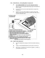
Delco Alternator – Internal Regulator. Use Paragraph 8.2.2.
9.3
Delco One-Wire Alternator. Use Paragraph 8.2.3.
9.4
GM Ignition (Start/Run) System. Use Paragraph 8.2.4.
10.0
CHARGING AND IGNITION SYSTEMS – JEEPS WITH FORD ENGINES
INSTALLED
10.1
Ford Alternator (2 configurations). Use Paragraph 8.2.1.
10.2
Ford Ignition (Start/Run) System. See Figure 10.1.
Note: If you are going to install an ammeter, see Section 7.3 first.
25
Содержание 10106
Страница 29: ...Figure 8 8 Ford Ignition Diagram Duraspark II Systems Figure 8 11 Ford Switch Connectors 24...
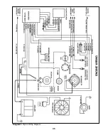
Страница 40: ...Diagram 1 Engine Wiring Diagram 35...
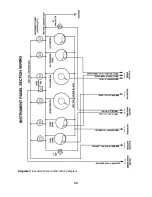
Страница 41: ...Diagram 2 Instrument Panel Section Wiring Diagram 35...
Страница 42: ...Diagram 3 Integrated Brake Lights Separate Turn Brake Lights 36...
Страница 44: ......


