11.0 CHARGING AND IGNITION SYSTEMS – JEEP WITH MOPAR ENGINES
INSTALLED
11.1
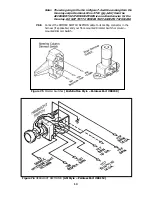
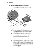
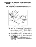
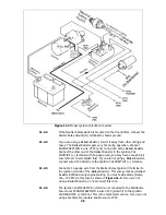
Mopar Alternator. See Figure 11.1.
Note: Your Alternator may not appear exactly as represented in Figure 11.1. The
circuits are wired the same way, though.
Figure 11.1 Mopar Alternator
11.1.1
Mopar uses one of two kinds of voltage regulators: An electronic regulator and a
mechanical one. The electronic voltage regulator is represented in Figure 11.1.
It does not matter how the two terminals are connected, so long as they are
BOTH connected. The mechanical regulator has terminals marked “F” (Field) and
“I” (Ignition). In contrast to the electronic regulator, it DOES make a difference
how these are connected.
11.1.2
Connect the provided 6 gauge red wire to the battery stud on the Alternator. The
other end of this wire will connect to the Midi fuse.
11.1.3
Connect ENGINE SECTION A wire #714 (wht) to the Alternator Field (F) terminal
as shown in Figure 11.1.
Connect a 14-gauge wire from the Alternator terminal where wire #714 is
connected to either of the ELECTRONIC Voltage Regulator terminals OR terminal
L of the MECHANICAL Voltage Regulator. On existing
Mopar harnesses, this
would be a blue wire.
27
Содержание 10106
Страница 29: ...Figure 8 8 Ford Ignition Diagram Duraspark II Systems Figure 8 11 Ford Switch Connectors 24...
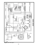
Страница 40: ...Diagram 1 Engine Wiring Diagram 35...
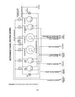
Страница 41: ...Diagram 2 Instrument Panel Section Wiring Diagram 35...
Страница 42: ...Diagram 3 Integrated Brake Lights Separate Turn Brake Lights 36...
Страница 44: ......

