


Consider the following guidelines.
5.5
A good exercise is to lay out the wire harness on the floor beside your Jeep and identify
all the SECTIONS.
5.6
You will want to route the harness through and around open areas. Inside edges provide
extra protection from hazards and also provide places for tie wraps, clips, and other
support.
5.7
Route the harness away from sharp edges, exhaust pipes, hood, trunk and door hinges.
5.8
Plan where harness supports will be located. Use a support every 12 inches unless the
harness routes under the floor carpet.
5.9
Allow enough slack in the harness at places where movement could possibly occur (body
to frame, frame to engine, etc.).
5.10
At wire ends, don’t depend on the terminals to support the harness. The weight of the
harness could cause terminals to disconnect or copper wire strands to break.
5.11
The wires should be bundled into groups. Use nylon ties, poly split loom, or tape.
6.0
WIRE HARNESS PHYSICAL INSTALLATION INSTRUCTIONS
CAUTION:
AGAIN REVIEW THE DIFFERENT SECTIONS OF THE PPPI WIRE
HARNESS AND THE INDIVIDUAL CIRCUIT CONNECTIONS. SEE TABLE
12-1. IT IS OF THE UTMOST IMPORTANCE THAT YOU DO NOT REMOVE
ANY EXISTING WIRING IN THE FOLLOWING AREAS:
•
Emission Control
•
Emission Control Microprocessor
•
Diagnostic Connector
•
Electronic Ignition
•
Interior Light
The preceding list may not be complete, depending upon your particular Jeep. You may, of
course, replace existing wiring and/or incorporate the listed areas into your new harness, but this
must be done one wire at a time. You may be able to obtain complete wiring diagrams for your
Jeep at your local public library, or from publishers such as Chilton’s or Mitchell’s. These can be
of invaluable help.
6.1
Rough Installation
CAUTION:
DISCONNECT THE POWER FROM YOUR VEHICLE BY REMOVING
THE NEGATIVE (BLACK) BATTERY TERMINAL FROM THE
BATTERY.
Note: Make no wire connections or permanent mounting of any kind at this
time!
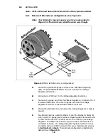
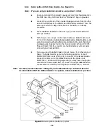
6.1.1
Position the fuse block in its mounting area.
6.1.2
Drill a 1-¼” (1.25”) hole (early models only) near the fuse block for engine and
headlight group wires to pass through (ENGINE SECTION, ENGINE SECTION A,
SINGLE 10-GAUGE red wire #716, and HEADLIGHT SECTION A).
5
Содержание 10106
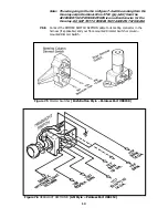
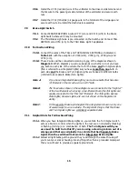
Страница 29: ...Figure 8 8 Ford Ignition Diagram Duraspark II Systems Figure 8 11 Ford Switch Connectors 24...
Страница 40: ...Diagram 1 Engine Wiring Diagram 35...
Страница 41: ...Diagram 2 Instrument Panel Section Wiring Diagram 35...
Страница 42: ...Diagram 3 Integrated Brake Lights Separate Turn Brake Lights 36...
Страница 44: ......