SECTION 4 - BOOM & PLATFORM
4-8
– JLG Lift –
3121623
pads from the top, sides and bottom of the base
boom section.
10.
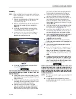
Using an overhead crane or suitable lifting
device, remove mid and fly boom sections from
base section. Note: When removing mid and fly
boom sections from base boom section, retract
wire rope must be dragged along with boom
sections.
11.
Remove hardware which secures the wear pads
to the rear end of mid boom section; remove the
wear pads from the top, sides and bottom of the
mid boom section.
12.
Remove hardware which secures the sheave
guards and sheave assemblies to mid boom sec-
tion, remove sheave assemblies from mid boom
section.
13.
Remove hardware which secures the wear pads
to the front of mid boom section; remove wear
pads from the top, sides and bottom of the mid
boom section.
14.
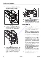
Using an overhead crane or suitable lifting
device, remove fly boom section from mid sec-
tion. Note: When removing fly boom section
from mid boom section, retract wire rope must
be dragged along with fly boom section.
15.
Remove hardware which secures the wear pads
to the rear end of fly boom section; remove wear
pads from the top, sides and bottom of the fly
boom section.
16.
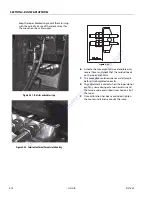
When removing wire rope from fly boom sec-
tion, push the cable into fly boom. Route wire
rope back through holes in the side of the fly
boom section.
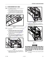
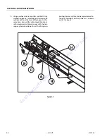
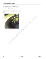
Figure 4-11.
4.3
INSPECTION
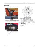
Checking Wear And Deformation Of Ropes And
Pulleys
If only one of the following situations is detected the
ropes or pulleys must be replaced.
1.
Check that there are no broken threads on the
surface of the rope, in the internal area or in cor-
respondence with the cable socket.
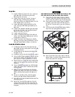
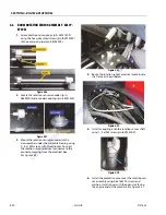
Figure 4-12.
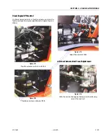
2.
Check that there are no signs of corrosion on the
rope.
3.
Check that there are no signs of kinking, crush-
ing or deformations of any type on the rope.
Figure 4-13.
4.
Check the condition of the fixing pins of the out-
let pulley and extensions return.
5.
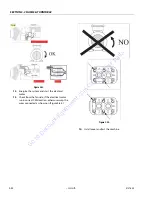
Check the wear of the pulley grooving using a
profile comparator. As indicated in the figure it is
necessary to check that the outline of the com-
parator corresponds with the base of the groov-
ing.
Figure 4-14.
6.
Check that there are no signs of ovalisation, wear
or any other type of deformation on the pulleys.
Go
to
Discount-Equipment.com
to
order
your
parts

