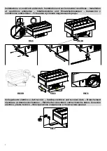
background image


15 

– Technical characteristics   

The  unit  is  supplied  together  with  a  plastic  bag  containing  this  instruction  manual  that  must  be  retained.  The  manual 
contains technical details, electrical diagrams and tables regarding the unit. 
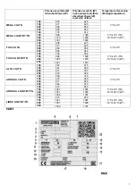
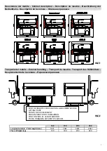
The technical details of the unit are also provided on the serial number plate (FIG. 8) which specifies: 
1.  Name and address of the manufacturer 
2.  Commercial name of the cabinet 
3.  Cabinet code 
4.  Cabinet serial number 
5.  Rating 
6.  Frequency 
7.  Max absorbed current 
8.  Max absorbed power 
9.  Max absorbed power during defrosting 
10.  Standard lighting power 
11.  Net display area 
12.  Type of cooling gas used 
13.  Weight of cooling gas loaded in each unit 
14.  Climate class and reference temperature (dry bulb) 
15.  Electrical safety factor 
16.  Work schedule number 
17.  Work order number 
18.  Year of manufacture 
19.  Heating capacity 
20.  QR code 
21.  EAC marking 

Warning:

  Neither  the  registration  plate  nor  the  warning  labels  must  be  removed  under  any  circumstance.  The 

manufacturer declines all responsibility if this warning is not followed. 
It  is  declared  that  the  equipment  complies  with  the  Decree  Law  25/01/1992  N.  108  in  accordance  with  CE  Directive 
89/109 concerning materials and objects destined to come into contact with foodstuffs. 
 

– Filling with products and use of the cabinet (startup) 

If the island  has been set at a sharp angle during positioning, wait at least three hours before starting it up to allow the 
lubricating oil to collect in the compressor. If this instruction is not followed the motor-driven condenser may be damaged 
beyond repair. 
The island may only be started up for the first time when points 3 and 4 have been completed. 
With the island turned off, proceed as follows: remove the protective plastic film on the inside and outside and then give 
the unit an initial clean (following the instructions given in point 10). 
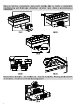
For the  BT/TN versions, move the selector in the motor compartment (FIG. 9) to the required  position  BT or TN before 
turning the unit on. 
Fit the plug in the socket (with the characteristics described  in  point 5) and operate any remote-control switch that may 
have  been  fitted.  A  slight  operating  noise  made  by  the  motor  and  the  display  turned  on  indicate  that  the  unit  has  been 
switched on.  
The display (FIG. 11) located on the front panel indicates the operating temperature of the island. The instruction booklet 
of  the  electronic  controls,  to  which  the  display  refers,  is  enclosed  with  the  instruction  manual  (this  device  cannot  be 
tampered with due to a safety password on which only a specialized technician is able to intervene). 
The unit starts its cooling cycle  and about 3  hours after it  has been switched  on, the product can be loaded (check the 
temperature shown on the display).  
The unit has been designed to display foodstuffs, it must maintain the temperature of the product and must not lower it, 
and  consequently,  the  product  must  only  be  placed  inside  the  unit  if  it  is  already  refrigerated  and  is  at  its  respective 
preservation temperature.  
Bottles and glass containers or jars full of liquid must not be stored in the BT versions as they may burst.  
For a correct preservation of the product, it is advisable: 

To use the special grids that are adjustable in height (when provided) to maintain the best ratio at all times between 
refrigerated space and product displayed (FIG. 12). 

Never exceed the maximum load line shown on the inside of the island (FIG. 13). 

Do not obstruct air grid that ensure the correct flow of air (FIG. 13). 

When  an  island  that  is  already  partially  loaded  with  goods  is  filled  with  more  products  (apart  from  adhering  to  the 
points referred to above), it is good practice to place the new foodstuffs under the existing ones. 

The  plug-in  islands  are  provided,  as  a  standard  fitting,  with  an  electronic  control.  The  thermostat  adjustment  and  the 
amount  of  gas  are  set  in  the  factory  and  any  tampering  with  these  settings  will  relieve  the  manufacturer  of  all 
responsibility. 
 

– Prohibitions and prescriptions 

Warning

: disconnect the cabinet from the power supply in case it is not used. The power supply has to be disconnected 

by the remote-control switch fitted upstream from the power socket.


Содержание Alya 2

Страница 1: ...MEGA 2 FOX 2 ALYA 2 ANTIGUA 2 LIBRA ISTRUZIONI D USO INSTRUCTION MANUAL MODE D EMPLOI BETRIEBSANLEITUNG INSTRUCCIONES DE USO...

Страница 2: ...choses qui serait d au non respect des instructions contenues dans ce manuel Au cas o l acqu reur du meuble frigorifique ne comprendrait pas une quelconque instruction mentionn e dans ce manuel d uti...

Страница 3: ...e Cabinet handling Transport du meuble Transport des K hlm bels Desplazamiento de la c mara 100 150 200 250 Lunghezza totale Total lenght mm 1041 1541 2041 2541 Peso Weight kg 120 160 200 240 FIG 1 PU...

Страница 4: ...tes Inbetriebnahme und Einsatzbedingungen Instalaci n y condiciones ambientales FIG 3 FIG 4A FIG 4B FIG 5 FIG 6 Collegamento elettrico e dati tecnici Cabling elettrical and tecnical data Branchement l...

Страница 5: ...501 1683 FOX 2 GI TN 100 605 423 0 C 2 C 150 617 625 200 850 836 250 866 952 FOX 2 GI BT BT TN 100 756 594 0 C 2 C TN 18 C 23 C BT 150 966 1020 200 1287 1425 250 1491 1673 ALYA 2 GI TN 100 557 375 0 C...

Страница 6: ...up and loading Mise en marche et chargement Inbetriebnahme und Best ckung Puesta en servicio y carga FIG 9 FIG 10 FIG 11 FIG 12 FIG 13 Manutenzione del mobile Unit maintenance Entretien du meuble War...

Страница 7: ...defrost probe IG Interruttore generale main switch Cc Cavo collegamento display quadro el Connecting cable display control board Tr Trasformatore transformer Ca Cavo alimentazione supply cable M Comp...

Страница 8: ...6 Schema elettrico Electrical diagram Sch ma lectrique Schalt plan Esquema el ctrico FIG 16 BT TN FIG 17 BT...

Страница 9: ...ntale per garantire il giusto giro d aria nel condensatore FIG 10 La presenza di oggetti davanti alla griglia di protezione del condensatore pregiudicherebbe il giusto funzionamento del mobile refrige...

Страница 10: ...avere eseguito i punti 3 e 4 Ad isola spenta procedere alla rimozione delle protezioni in pellicola plastica presenti all interno e all esterno dopodich eseguire una prima pulizia seguendo le indicazi...

Страница 11: ...i mobili in caso di mal funzionamento chiamare un tecnico specializzato Le isole plug in sono dotate di un sistema d evaporazione automatica dell acqua di sbrinamento buona norma controllare almeno un...

Страница 12: ...l mobile Per il rispetto ecologico dell ambiente ed in conformit alle norme vigenti dei singoli paesi suddividere le parti del mobile per lo smaltimento e o recupero Tutte le parti che costituiscono i...

Страница 13: ...istenza antiappannante 2 uscita I1 Selezionatore BT TN S1 Sonda temperatura S2 Sonda sbrinamento Lo schema in FIG 17 riferito alle isole BT COM Comando elettronico isole D Display elettronico C1 Compr...

Страница 14: ...r i tecnici incaricati di eseguire interventi sul banco frigorifero Simbolo Descrizione Protezione degli occhi Guanti di Protezione Calzature di sicurezza Simbologia di Sicurezza per una immediata inf...

Страница 15: ...o WEEE RAEE professionali In caso di sostituzione del prodotto con altro nuovo l utilizzatore pu chiedere al venditore il ritiro di quello vecchio indipendentemente dal suo marchio responsabilit del p...

Страница 16: ...ntal conditions differ from those provided for or the counters are exposed to draughts of air exceeding 0 2 m s or radiating heat the level of performance will be lower than the standard one To avoid...

Страница 17: ...unit on Fit the plug in the socket with the characteristics described in point 5 and operate any remote control switch that may have been fitted A slight operating noise made by the motor and the dis...

Страница 18: ...ration system of the water it is good practice to check the level of the water in the evaporating basin located near the motor compartment at least once a month this operation must be carried out with...

Страница 19: ...als that are not classifiable as urban waste except for the metallic parts that are not classified as special waste in most countries As regards the parts of the refrigeration circuit that is the refr...

Страница 20: ...selector S1 Temperature probe S2 Defrost probe The electrical diagram shown in Fig 17 is related to BT islands Legend COM Electronic Command for BT TN islands D Electronic Display C1 Compressor No 1 C...

Страница 21: ...f The following personal protective equipment are compulsory for technicians who work on the counter Symbol Description Eyes protection Protective gloves Safety Shoes Safety Symbols for immediate noti...

Страница 22: ...and recycling of professional WEEE RAEE In case of trade in of the old product for a new one the user can ask the seller to take delivery of the old one no matter what the brand The manufacturer is r...

Страница 23: ...e EN ISO 23953 1 2 la classe climatique 3 pr voyant une temp rature ambiante de 25 C avec une humidit relative de 60 Il est recommand de laisser un espace ad quat devant le meuble frigorifique afin de...

Страница 24: ...concernant les mat riaux et les objets destin s tre en contact avec des produits alimentaires 7 Chargement des produits et utilisation du meuble frigorifique mise en marche Si l lot a t fortement inc...

Страница 25: ...pulseurs inflammables dans cet appareil 9 D givrage du meuble et vaporation de l eau de condensation Le cycle de d givrage indispensable au bon fonctionnement du meuble frigorifique est actionn par la...

Страница 26: ...V rifier que le meuble frigorifique soit bien en plan et que les conditions ambiantes respectent les conditions mentionn es au point 4 Si le probl me persiste apr s toutes ces v rifications adressez v...

Страница 27: ...ti bu e Le sch ma de la FIG 16 se r f re aux lots BT TN L gende COM Commande lectronique lots BT TN D Display Ecran lectronique KE Clef lectronique C1 Compresseur 1 C2 Compresseur 2 F1 Ventilateur d v...

Страница 28: ...techniciens qui travaille sur le meuble frigorifique Symbole Description Protection des yeux Gants de protection Chaussures de s curit Symboles de s curit pour la notification imm diate des situation...

Страница 29: ...emplacement du produit avec un autre nouveau l utilisateur peut demander au vendeur le retrait du vieux produit ind pendamment de sa marque C est le fabricant qui est responsable de rendre faisable la...

Страница 30: ...keit von 60 vorsieht Es muss auf der Frontseite ausreichend Platz f r die Abk hlung und die Wartung des Verfl ssigers vorhanden sein Abb 10 Die Aufstellung von Gegenst nde vor dem Schutzgitter des Agg...

Страница 31: ...hrift EG 89 109 betreffend Materialien und Gegenst nde f r den Kontakt mit Lebensmitteln entspricht 7 Best ckung und Einsatz der Truhe Inbetriebnahme Sollte die Truhe w hrend dem Aufstellen eine sehr...

Страница 32: ...rungen BT Option bei den Ausf hrungen TN gleichzeitig sind die Verdichter eingestellt und dadurch wird der Verdampfer von etwaigen Eisbildungen befreit Die Anzahl der Abtauzyklen serienm ig 3 Abtauzyk...

Страница 33: ...stausch von mechanischen elektrischen Bestandteilen oder Kompressoren notwendig ist sollen nur vom Hersteller gelieferte Originalersatzteile verwendet werden 14 Demontage und Entsorgung des K hlm bels...

Страница 34: ...auheizung R2 Glasscheibeheizung 1 Anschluss R3 Glasscheibeheizung 2 Anschluss I1 W hlschalter BT TN S1 Temperaturf hler S2 Abtauf hler Das Schema der Abb 17 bezieht sich auf die Einzeltheken BT Zeiche...

Страница 35: ...ligatorisch um die Wartung auf die Theke zu bearbeiten Symbol Beschreibung Augenschutz Schutzhandschuhe Sicherheits Schuhe Sicherheit Symbole f r sofortige Benachrichtigung von gef hrlichen Situatione...

Страница 36: ...u bergeben Bei Ersatz des Produkts mit einem neuen kann der Benutzer beim Verk ufer die R cknahme des alten Ger ts fordern und dies unabh ngig von der Marke Es ist Pflicht des Herstellers das Recyclin...

Страница 37: ...fieren seg n la normativa internacional EN ISO 23953 1 2 a la clase clim tica ambiental 3 que prev una temperatura ambiente de 25 C con una humedad relativa del 60 Se necesita un espacio frontal adecu...

Страница 38: ...cionamiento Si la c mara ha sufrido inclinaciones importantes durante su colocaci n hay que esperar tres horas como m nimo antes de ponerla en marcha para que el aceite lubrificante se recoja en el co...

Страница 39: ...a c mara de refrigeraci n se acciona con el mando electr nico que mediante resistencias blindadas situadas en el evaporador s lo en las versiones BT accesorio para las TN y parando simult neamente el...

Страница 40: ...enchufar la c mara de la corriente No usar agua para apagar las posibles llamas si no nicamente extintores a seco 13 Asistencia t cnica Cuando se necesite la intervenci n de personal t cnico de asiste...

Страница 41: ...or 2 F1 Ventilador evaporador R1 Resistencia de desescarche R2 Resistencia antiempa amiento 1a salida R3 Resistencia antiempa amiento 2a salida I1 Seleccionador BT TN S1 Sonda temperatura S2 Sonda des...

Страница 42: ...l necesarios por los t cnicos para trabajar en la exibidora S mbolo Descripci n Protecci n de los ojos Guantes de protecci n Zapatos de seguridad S mbolos de seguridad para la notificaci n inmediata d...

Страница 43: ...n y reciclaje WEEE RAEE profesionales Si el producto se sustituye con otro nuevo el utilizador puede solicitar al vendedor que retire el viejo independientemente de la marca El fabricante es responsa...

Страница 44: ...42 1 2 4 4 3 C 55 C 4 4 4 3 EN ISO 23953 1 2 25 C 60 5 15 16 17 3 _10...

Страница 45: ...43 6 1 2 3 4 5 6 7 8 9 10 11 12 13 14 15 16 17 18 19 20 QR 21 EAC 7 BT TN BT TN...

Страница 46: ...44 8 IEC60335 2 89 IEC60335 2 89 9 TN TN TN IEC60335 2 89 10 11...

Страница 47: ...45 TN 12 TN 13 14 CO2 HFC GWP OSCARTIELLE R 290 GWP 100 3 R 134A GWP 100 1300 R 452A GWP 100 2140 R 404A GWP 100 3750 3 D P R n 147 15 2006 3 4 15...

Страница 48: ...46 16 BT Ce St Ss IG Cc Tr Ca M Lu D Vm Ve Ra BT TN COM BT TN D KE C1 C2 F1 R1 R2 R3 I1 BT TN S1 S2 BT COM D C1 C2 F1 R1 R2 R3 S1 S2 17 http www oscartielle it conformity...

Страница 49: ...47...

Страница 50: ...Oscartielle S p A 2012 19 CE WEEE Waste Electrical and Electronic Equipment RAEE 1 2011 25 2010 DL 194 2009 WEEE RAEE Oscartielle S p A WEEE RAEE Orglime 49 2014 27 2014 2012 19 CE 2011 65 CE RoHS...

Страница 51: ...Oscartielle Spa Via Boffalora 1 A 24048 Treviolo BG 020 2011 TP TC 004 2011 010 2011...

Страница 52: ...al features without notice OSCARTIELLE dont la politique est celle d un perfectionnement continu se r serve le droit de varier les d tails techniques sans pr avis Die Firma OSCARTIELLE dessen Bestrebe...

Отзывы: