Garmin G3X Touch Скачать руководство пользователя страница 1

G3X


Pilot’s Guide

Содержание G3X Touch

Страница 1: ...G3X Pilot s Guide ...

Страница 2: ......

Страница 3: ...SYSTEM OVERVIEW FLIGHT INSTRUMENTS EIS CNS INTERFACE GPS NAVIGATION FLIGHT PLANNING HAZARD AVOIDANCE ADDITIONAL FEATURES AFCS ANNUNCIATIONS ALERTS APPENDIX INDEX ...

Страница 4: ......

Страница 5: ...copied transmitted disseminated downloaded or stored in any storage medium for any purpose without the express written permission of Garmin Garmin hereby grants permission to download a single copy of this manual and of any revision to this manual onto a hard drive or other electronic storage medium to be viewed for personal use provided that such electronic or printed copy of this manual or revis...

Страница 6: ...ll available navigation sources including the information from other NAVAIDs visual sightings charts etc For safety purposes always resolve any discrepancies before continuing navigation WARNING The displayed minimum safe altitudes MSAs are only advisory in nature and should not be relied upon as the sole source of obstacle and terrain avoidance information Always refer to current aeronautical cha...

Страница 7: ... any thunderstorm identified as severe or giving an intense radar echo WARNING Because of variation in the earth s magnetic field operating the G3X within the following areas could result in loss of reliable attitude and heading indications North of 72 North latitude at all longitudes South of 70 South latitude at all longitudes North of 65 North latitude between longitude 75 W and 120 W Northern ...

Страница 8: ...ditions relieve the pilot s responsibility to see and avoid other aircraft WARNING Do not rely solely upon the display of traffic information to accurately depict all of the traffic within range of the aircraft Due to lack of equipment poor signal reception and or inaccurate information from aircraft or ground stations traffic may be present that is not represented on the display WARNING For safet...

Страница 9: ...the State of California to cause cancer birth defects or reproductive harm This notice is being provided in accordance with California s Proposition 65 If you have any questions or would like additional information please refer to our web site at www garmin com prop65 NOTE Interference from GPS repeaters operating inside nearby hangars can cause an intermittent loss of attitude and heading display...

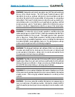
Страница 10: ...Garmin G3X Pilot s Guide 190 01115 00 Rev K Warnings Cautions Notes Blank Page ...

Страница 11: ...Synthetic Vision Added mach number to configurable Data Fields E April 2011 System Software Version 3 00 to 3 10 Added ability to import export flight plans using the SD card Added Softkeys to Nearest Airports Page to quickly show hide private airports and heliports Removed ability to adjust Roll Mode reference using the FMS Joystick System Software Version 3 10 to 3 20 Added ability to display ch...

Страница 12: ...m Added automatic sync of altimeter setting to local terrain elevation when FMS Joystick is pressed and held while BARO Softkey is selected and aircraft is stationary on the ground Added display of displaced runway threshold distance to Airport Review Page Added menu options to the Waypoint Page to quickly view the depar ture and destination airports Added menu option and softkey to the FPL VNAV P...

Страница 13: ...sion display Added ability to change the layout of PFD1 between full screen and split screen in normal mode via the Display Setup Page Added arrows to PFD traffic and terrain messages to indicate traffic and terrain alerts which are outside the Synthetic Vision field of view Added display of peak EGT temperature to bar graph display on Engine Page when Lean Mode is active Added softkey to Terrain ...

Страница 14: ...ed Changed screenshot utility to be activated when Menu key is pressed and held Changed selected altitude data field on PFD to flash in conjunction with armed autopilot VNAV indicator if an altitude has not been selected prior to VNAV descent Changed Fuel Calculator display on Engine page to show fuel quantity and pressure gauges if space is available Changed wind direction display on PFD to use s...

Страница 15: ...on 7 30 to 7 40 Added support for Rotax 966385 sensor for CHT and oil temperature Improved lean assist detection of false peaks due to small temperature fluctuations System Software Version 7 40 to 8 00 Added GMC 305 AFCS Controller support Added GSU 25 AHRS support Added GAP 26 Pitot AOA Mast support Added GSA 28 Auto Pilot Servo support Added GEA 24 Engine Airframe support ...

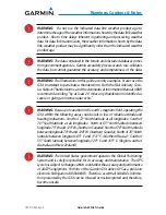
Страница 16: ...Garmin G3X Pilot s Guide 190 01115 00 Rev K RR 6 Blank Page ...

Страница 17: ...Display Operation 20 PFD Display Configuration 23 G3X System Annunciations 24 AHRS Operation 24 1 7 Accessing System Functionality 28 Menus 28 Data Entry 29 Pages 31 Main Page Softkeys 36 Flight Planning Softkeys 48 Nearest Page Softkeys 49 1 8 Accessing the Information INFO Page 49 Viewing GPS Receiver Status 49 Position 52 Data Fields and Layout Full Screen MFD 54 1 9 System Settings 55 Transpon...

Страница 18: ...105 ENG Page Softkeys Example Configuration 109 3 2 Lean Assist Mode Optional 109 3 3 Fuel Calculator Optional 113 Fuel Calculator Softkeys 115 Confirming Fuel Quantity 116 3 4 CAS Messages Optional 118 Section 4 CNS Interface 121 4 1 Auto tuning Frequencies Optional 121 4 3 Remote Transponder Interface Optional 124 Transponder Mode Selection 127 Entering a Transponder Code 128 IDENT Function 129 ...

Страница 19: ...Flight Plan Creation Using the G3X 174 6 3 Flight Plan Storage USing the G3X 176 6 4 Flight Plan Activation Using the G3X 177 6 5 Flight Plan Editing 178 Adding Waypoints to an Existing Flight Plan 178 Editing Flight Plan Speed Fuel and or Name 180 Copying Flight Plans 183 Deleting Flight Plans 183 Inverting a Flight Plan 185 Importing Exporting Flight Plans 186 6 6 Approaches Without External Nav...

Страница 20: ...ory Data 288 8 6 SiriusXM Radio Entertainment Optional 290 Activating SiriusXM Satellite Radio Services 290 Using SiriusXM Radio 291 8 7 Vertical Power Optional 295 8 8 Electronic Checklists Optional 297 8 9 Flight Data Logging 297 Section 9 Automatic Flight Control Systems Optional 299 AFCS System Architecture 299 G3X AFCS Installations Options 301 Control Wheel Steering CWS Optional 301 G3X AFCS...

Страница 21: ...FO Page 371 10 3 Audio Alerts 376 Voice Alerts 376 AOA Aural Alert 376 10 4 PFD Annunciations and Alerting Functions 377 Uncertain Heading 377 External Navigator Messages Optional 377 CAS Messages Optional 378 Terrain Annunciations 379 Traffic Annunciations 380 AHRS Alerts Optional 381 AFCS Alerts Optional 382 Vertical Power Fault Indications 384 Section 11 Appendices 385 Appendix A Data Field Opt...

Страница 22: ...nciations 420 Unusual Attitudes 421 Reversionary Mode Full Screen 422 AFCS Reversionary Mode 422 Failure of the External GPS Navigation Source 422 Synthetic Vision Troubleshooting 424 Appendix G Display Symbols 425 VFR Symbols 425 IFR Symbols 426 Airspace Symbols 428 Appendix H Glossary 431 Appendix I License Agreement and Warranty 437 Contact Garmin 437 Software License Agreement 437 Limited Warr...

Страница 23: ...nformation to the pilot usingWideVGA 800x480 flat panel color display s The seven inch diagonally measured display s provides 22 square inches each of viewing area 1 1 LINE REPLACEABLE UNITS The system consists of the following Line Replaceable Units LRUs Garmin Display Unit GDU 375 with XM Single Display Split Primary Flight Display PFD Multi Function Display MFD Multiple Displays MFD recommended...

Страница 24: ...ic system and outside air tem perature OAT sensor Engine Airframe Unit Receives and processes signals from the engine and airframe sensors AHRS Provides aircraft attitude and heading information to the PFD The AHRS contains advanced sensors including accelerometers and rate sensors and interfaces with the Magnetometer to obtain magnetic field information with the ADC to obtain air data and with th...

Страница 25: ...and the Attitude and Heading Reference System AHRS ADC Processes data from the pitot static system and outside air tem perature OAT sensor AHRS Provides aircraft attitude and heading information to the PFD The AHRS contains advanced sensors including accelerometers and rate sensors and interfaces with the Magnetometer to obtain magnetic field information with the ADC to obtain air data and with th...

Страница 26: ...netometer Measures the local magnetic field and sends data to the AHRS for processing to determine aircraft magnetic heading This unit receives power directly from the AHRS and communicates with it via an RS 485 digital interface GMU 44 GMU 22 GTP 59 Temperature Probe Provides raw air temperature data GTP 59 GAP 26 Pitot Probe Sends dynamic air pressure for airspeed altitude and angle of attack AO...

Страница 27: ... CNS Interface GPS Navigation Flight Planning Hazard Avoidance Additional Features AFCS Annun Alerts Appendix Index GSA 28 Auto Pilot Servo Used for automatic control of pitch roll and yaw GSA 28 GEA 24 Engine and Airframe Unit Receives and processes signals from the engine and airframe sensors GEA 24 ...

Страница 28: ...tem Overview Flight Instruments EIS CNS Interface GPS Navigation Flight Planning Hazard Avoidance Additional Features AFCS Annun Alerts Appendix Index GAD 29 ARINC 429 interface Transmits and receives ARINC 429 signals for interface to panel mount IFR GPS navigators ...

Страница 29: ...G3X Standard Panel Split Screen GSU 73 G3X Standard Panel Split Screen GSU 25 GMU 44 22 Magnetometer Heading GTP 59 Temperature Probe GAP 26 Pitot AOA Probe GSU 25 Garmin Sensor Unit GDU 370 or 375 XM AHRS Attitude Heading Rate of Turn Slip Skid AOA Air Data Computer OAT Airspeed Altitude Vertical Speed Split PFD MFD GMU 44 22 Magnetometer Heading GSU 73 Garmin Sensor Unit GDU 370 or 375 XM AHRS A...

Страница 30: ...Magnetometer Heading GTP 59 Temperature Probe GAP 26 Pitot AOA Probe GSU 25 Garmin Sensor Unit AHRS Attitude Heading Rate of Turn Slip Skid AOA Air Data Computer OAT Airspeed Altitude Vertical Speed GEA 24 Engine Airframe Unit GSU 73 Garmin Sensor Unit GDU 370 or 375 XM AHRS Attitude Heading Rate of Turn Slip Skid Air Data Computer OAT Airspeed Altitude Vertical Speed Engine Airframe Unit Split PF...

Страница 31: ...l would have the left GDU configured as a full screen PFD and the right GDU configured as a full screen MFD The following is an example of a upgraded G3X panel using a GDU 370 and a GDU 375 however two GDU 370s can be used if SiriusXM is not needed G3X Upgraded Panel Full Screen GSU 73 GMU 44 22 Magnetometer Heading GSU 73 Garmin Sensor Unit GDU 370 PFD AHRS Heading Attitude Rate of Turn Slip Skid...

Страница 32: ...e Additional Features AFCS Annun Alerts Appendix Index G3X Upgraded Panel Full Screen GSU 25 GDU 370 PFD GDU 375 MFD GMU 44 22 Magnetometer Heading GTP 59 Temperature Probe GAP 26 Pitot AOA Probe GSU 25 Garmin Sensor Unit Air Data Computer OAT Airspeed Altitude Vertical Speed GEA 24 Engine Airframe Unit V AHRS Attitude Heading Rate of Turn Slip Skid AOA CAN BUS ...

Страница 33: ...dex G3X Upgraded Panel Dual ADAHRS GMU 44 22 Magnetometer Heading GTP 59 Temperature Probe GAP 26 Pitot AOA Probe GSU 25 Garmin Sensor Unit AHRS Attitude Heading Rate of Turn Slip Skid AOA Air Data Computer OAT Airspeed Altitude Vertical Speed GSU 73 Garmin Sensor Unit AHRS Attitude Heading Rate of Turn Slip Skid Air Data Computer OAT Airspeed Altitude Vertical Speed Engine Airframe Unit GDU 370 P...

Страница 34: ... OAT Airspeed Altitude Vertical Speed GDU 370 PFD GDU 375 MFD GSU 25 Garmin Sensor Unit AHRS Attitude Heading Rate of Turn Slip Skid AOA Air Data Computer OAT Airspeed Altitude Vertical Speed GEA 24 Engine Airframe Unit GAD 29 ARINC 429 interface SPLIT SCREEN VS FULL SCREEN CONFIGURATIONS Various combinations of split and full screen configurations are available in systems with 2 or more GDUs For ...

Страница 35: ...eg of a published procedure These waypoints and associated course line are made available for monitoring purposes only In a configuration which includes one or more external GPS navigators i e GTN or GNS Series the G3X displays the selected external GPS Navigator s flight plan and guidance information When using an external GPS navigator with the G3X press the INTERNAL Softkey on the Active Flight...

Страница 36: ...t Format When using a WAAS enabled external GPS navigator i e GNS 430W 530W GNS 480 or any GTN Series navigator and configuring an RS 232 input for MapMX instead of Aviation In a more accurate depiction of the flight plan legs are displayed on the moving map i e holds procedure turns etc Non WAAS external navigators do not support MapMX Refer to the G3X Installation Manual for more information EXT...

Страница 37: ...Softkeys Hardkeys FMS Joystick Range RNG Key SD Card Slot Display Bezel 7 WVGA 800x480 Color Display 1 3 SECURE DIGITAL SD CARDS NOTE Refer to Appendix C for more information on SD Card use and data bases The G3X data card slot uses Secure Digital SD cards and is located on the upper right side of the display bezel s The SD card can be used for software updates checklist files flight data logging ...

Страница 38: ...ce Additional Features AFCS Annun Alerts Appendix Index Installing an SD Card 1 Insert the SD card in the SD card slot with the card contacts facing the display the card should be flush with the face of the bezel 2 To eject the card gently press on the SD card to release the spring latch Display Bezel SD Card Slot SD Card Slot 1 4 G3X CONTROLS 9 3 2 4 5 6 7 8 1 ...

Страница 39: ...h the HDG or HDG ROLL Softkey selected press and hold the FMS Joystick to sync to the current heading With the appropriate autopilot mode selected move the FMS Joystick up down to adjust the mode reference for Vertical Speed Altitude Hold Target Airspeed for IAS mode GMC 305 only and Pitch Hold modes or move the FMS Joystick left right to decrease the mode reference for Roll Hold mode 3 ENT Key Pr...

Страница 40: ...bove the bezel key on the display 1 5 SYSTEM POWER UP During system initialization the AHRS displays the message AHRS ALIGN KEEP WINGS LEVEL over the attitude indicator The AHRS should display valid attitude and heading fields typically within the first minute of power up The AHRS can align itself both while taxiing and during level flight System Initialization Current database information is disp...

Страница 41: ...anning Hazard Avoidance Additional Features AFCS Annun Alerts Appendix Index Database Information Pressing the ENT Key acknowledges this information After acknowledgement of the database information the pilot is prompted to acknowledge a data link weather advisory Data link Weather Advisory Pressing the ENT Key acknowledges this information ...

Страница 42: ...s with all the GDUs configured to use their own internal GPS receivers any remaining GDUs will attempt to approximate their position using GPS data from an external GPS navigator if configured In normal operating mode the PFD presents graphical flight instrumentation attitude heading airspeed altitude vertical speed replacing the traditional flight instrument cluster Split Screen Only The PFD occu...

Страница 43: ... Mode In normal mode the displays can be configured to have a dedicated PFD and MFD or have an optional split screen PFD G3X Full Screen Normal Mode G3X Normal Mode Optional Split Screen PFD Full Screen PFD MFD Configuration Reversionary Mode In the event of a display failure the G3X System automatically switches to reversionary backup mode In reversionary mode all flight information is presented ...

Страница 44: ... Pages will no longer be available since the XM receiver resides in the GDU 375 G3X Full Screen Reversionary Mode Failed PFD Multi Display Normal Mode In normal mode an example Multi Display system includes a pilot side PFD PFD1 MFD and co pilot side PFD PFD2 PFD1 can also be configured as a split screen PFD2 can be configured as a split screen or PFD MFD full screen PFD page and full screen MFD p...

Страница 45: ...the FMS Joystick to highlight System Setup and press the ENT Key 3 Turn or move the FMS Joystick to highlight Display and press the ENT Key 4 Move the FMS Joystick to highlight the PFD Display Layout field 5 Turn the FMS Joystick to highlight Auto or Split 6 Press the FMS Joystick the CLR Key the EXIT Softkey or the MENU Key to return to the previous page Changing the PFD2 Display Layout If the sy...

Страница 46: ...FD Initialization AHRS OPERATION The Attitude and Heading Reference System AHRS performs attitude heading and vertical acceleration calculations for the G3X System utilizing GPS magnetometer and air data in addition to information from its internal sensors Attitude and heading information are updated on the PFD while theAHRS receives appropriate combinations of information from the external sensor...

Страница 47: ...l b e e e e Air Data le e e e l bl b e e e e e Magnetometer Data unavailable available l bl b e e e e e le e e e GPS Data l ble e e e e le e e Magnetometer Data le e e e u u Air Data Loss of GPS magnetometer or air data inputs is communicated to the pilot by message advisory alerts Any failure of the internalAHRS inertial sensors results in loss of attitude and heading information indicated by red...

Страница 48: ... all attitude and heading information In installations that include multiple AHRS units G3X supports up to three AHRS sources if data from anAHRS source is lost the G3X will automatically switch sources when a failure is detected Reversionary sensor selection is annunciated in a window on the right side of the PFD These annunciations reflect reversionary sensors selected on the PFD Pressing the Me...

Страница 49: ...90 01115 00 Rev K 27 System Overview System Overview Flight Instruments EIS CNS Interface GPS Navigation Flight Planning Hazard Avoidance Additional Features AFCS Annun Alerts Appendix Index Dual AHRS Reversionary Sensor Window ...

Страница 50: ...e The menu will display No Options when there are no options for the page selected Navigating the page menu 1 Press the MENU Key once to display the Page Menu 2 Turn or move the FMS Joystick to scroll through a list of available options a scroll bar always appears to the right of the window box when the option list is longer than the window box 3 Press the ENT Key to select the desired option 4 Pr...

Страница 51: ...ired identifier based on the characters being entered In this case if the desired identifier appears use the ENT Key to confirm the entry without entering the rest of the identifier manually This can save the pilot from having to enter all the characters of the identifier Besides character by character data entry the system also provides a shortcut for entering waypoint identifiers When the cursor...

Страница 52: ...splay a list of recent waypoints RECENT WPTS nearest airports NRST APTS or flight plan waypoints FPL WPTS b Move the FMS Joystick to highlight the desired waypoint from the list and press the ENT Key Waypoint Entry on Waypoint Page Split Screen Or a Turn the FMS Joystick clockwise to select a character for the first placeholder Data Entry Turning the FMS Joystick clockwise scrolls through the alph...

Страница 53: ...he lower portion of the display directly above the softkey bar The right side of the page navigation bar shows a list of abbreviated names for each of the pages and the left side shows the name of the current page Press the FMS Joystick to toggle input focus between the Page Navigation Bar and interaction with the current page i e turning the page cursor on off When the Page Navigation Bar is high...

Страница 54: ... the FMS Joystick The Traffic TRF Page can be displayed or removed from the Display Setup menu Selecting a main page using the FMS Joystick 1 If necessary press the FMS Joystick to begin interaction with the Page Navigation Bar 2 Turn the FMS Joystick until the desired page is selected PFD split screen only MAP WPT WX TER TRF optional XM INFO ENG Main Pages PFD Page PFD split screen Traffic Page T...

Страница 55: ...nal Features AFCS Annun Alerts Appendix Index Main Pages Split Screen Displaying Removing the Traffic Page 1 Press the MENU Key twice to display the Main Menu 2 Turn or move the FMS Joystick to highlight System Setup and press the ENT Key 3 Turn or move the FMS Joystick to highlight Display and press the ENT Key 4 Move the FMS Joystick to highlight the Traffic Page field ...

Страница 56: ...st Pages contain the following information APT Airport identifier bearing distance length of the longest runway and common traffic advisory CTAF or tower frequency WX Airport Weather GDU 375 Only identifier bearing distance METAR text and ATIS AWOS or ASOS frequency VOR VHF Omnidirectional Radio Beacon identifier facility type symbol bearing distance and frequency NDB Non Directional Beacons ident...

Страница 57: ...idance Additional Features AFCS Annun Alerts Appendix Index Nearest Pages Split Screen Nearest Pages NRST Nearest Airports APT Nearest User Waypoints USR Nearest Airport Weather WX GDU 375 Nearest Cities CTY Nearest VORs VOR Nearest ARTCC ATC Nearest NDBs NDB Nearest FSS FSS Nearest Intersections INT Nearest Airspace ASPC Visual Reporting Point VRP Atlantic ...

Страница 58: ... softkeys are located along the bottom of the display s The softkeys shown depend on the softkey level or page being displayed The bezel keys below the softkeys can be used to select the appropriate softkey When a softkey is selected its color undergoes a momentary change to black text on blue background then automatically switches to black text on gray background and remains this way until it is ...

Страница 59: ... or OBS CRS Allows the pilot to adjust the OBS course or VOR CRS Allows the pilot to adjust the VOR course or LOC CRS Allows the pilot to adjust the localizer course CDI SRC Toggles between available NAV sources when configured BARO Allows the pilot to change the barometric setting and enables the second level BARO Softkeys ALT Allows the pilot to adjust the selected altitude MINIMUMS XX GAL BARO ...

Страница 60: ...PDR CRS when the pilot can control the navigation course XPDR IDENT CODE BACK IDENT MODE CRS VFR ALT ON STBY GND BACK SET ID BACK CODE XPDR CRS or OBS CRS VOR CRS LOC CRS or or or IDENT Sends a distinct identity indication to Air Traffic Control ATC CRS subdued A navigation source is not selected or OBS CRS Allows the pilot to adjust the OBS course or VOR CRS Allows the pilot to adjust the VOR cou...

Страница 61: ...by mode When in standby mode the remote transponder will not reply to any interrogations Press and hold to put the transponder in Ground GND Mode Ground Mode is normally selected automatically when the aircraft is on the ground ON Generates Mode A and Mode S replies but Mode C altitude reporting is inhibited ALT Selects ALT Mode All transponder replies requesting altitude information are provided ...

Страница 62: ...mode AP NAV Selects deselects navigation mode Cancels GS Mode if LOC Mode is either active or armed Cancels GP Mode if GPS Mode is either active or armed Cancels LOC Mode if GPS Mode is active and LOC Mode is armed ALT PTCH Initial press allows the pilot to adjust the selected altitude and displays the vertical mode softkeys subsequent press returns to top level softkeys ALT PTCH Softkey selected ...

Страница 63: ...E SOFTKEYS MAP TERRAIN WEATHER TRAFFIC MAP Enables second level Map Page softkeys TERRAIN Displays removes terrain awareness information WEATHER Displays removes weather information TRAFFIC Displays removes traffic information MAP VFR MAP BACK IFR MAP TOPO BACK Press the BACK Softkey to return to the top level softkeys SAT VIEW HIGH AWY LOW AWY IFR MAP VFR MAP VFR MAP Softkey selected IFR MAP Disp...

Страница 64: ... Returns to top level softkeys WAYPOINT PAGE SOFTKEYS Waypoint WPT Page Softkeys Split Screen INFO RUNWAY CHART AOPA WEATHER DIRECTORY INFO CHART AOPA WEATHER DIRECTORY Waypoint WPT Page Softkeys Full Screen INFO Displays waypoint information RUNWAY Displays runway information split screen only CHART Displays optional FliteCharts AOPA or DIRECTORY Displays airport directory information WEATHER Dis...

Страница 65: ...rrain TER Page Softkeys Full Screen MAP Displays the Terrain Page Map View PROFILE Displays the Terrain Page Profile View SETTINGS Displays the Terrain Setup Page DISABLE Toggles terrain alerts on off TRAFFIC PAGE SOFTKEYS OPTIONAL GDL 39 OR GTS 800 VOL BACK VOL MUTE VOLUME Press the BACK Softkey to return to the top level softkeys INFO CHANNEL VOLUME CATEGORY PRESETS DISABLE FLT ID BACK UNREST AB...

Страница 66: ...nt phase of flight NORMAL Displays non threat and proximity traffic from 2700 feet above the aircraft to 2700 feet below the aircraft Typically used during enroute phase of flight ABOVE Displays non threat and proximity traffic from 9000 feet above the aircraft to 2700 feet above the aircraft Typically used during enroute phase of flight UNREST Unrestricted All traffic is displayed INFO Softkey se...

Страница 67: ...CS Annun Alerts Appendix Index VOLUME Enables second level VOLUME softkeys Press and hold to toggle Mute on off VOL BACK VOL MUTE VOLUME Press the BACK Softkey to return to the top level softkeys VOL Decreases XM audio volume VOL Increases XM audio volume MUTE Toggles XM audio on off BACK Returns to top level softkeys INFO PAGE SOFTKEY MESSAGES MESSAGES Displays system status messages ...

Страница 68: ...s Full Screen SYS VIEW SYSVIEW is only available on a Split Screen installation and toggles between a list of configured devices and the schematic showing the connected devices XXXX Device Sensitive Softkey e g ON TRIM UP TRIM L or FLAPS UP XXXX Device Sensitive Softkey e g OFF TRIM DN TRIM R or FLAPS DN AUTO Only appears when the landing light is selected and it has been configured for wig wag RE...

Страница 69: ...TRIM TEMPS Displays additional engine gauges as required optional LEAN Activates deactivates Lean Assist optional FUEL Displays Fuel Calculator optional XX GAL XX GAL XX GAL FUEL FUEL RESET optional optional optional RESET Resets fuel used to zero and fuel remaining to full tanks XX GAL Sets fuel remaining to the full tank quantity where XX is the airframe specific full fuel quantity XX GAL Sets f...

Страница 70: ...Optional Allows the pilot to select the internal GPS flight plan source EXTERNAL Optional Allows the pilot to select the external GPS flight plan source EXIT Exits the Flight Plan Pages FLIGHT PLAN LIST PAGE SOFTKEYS ACTIVATE NEW EXIT IMPORT EXPORT ACTIVATE Displays the Activate Flight Plan Window NEW Displays the New Flight Plan Window IMPORT Displays the available flight plans to import from the...

Страница 71: ... 2 for the INFO Page System Status Messages NOTE A System Status Message and the word External appearing next to the GPS Status indicates that the display connected to the GPS antenna is unavailable and the remaining display s are using the external GPS navigator for 2D GPS position data In this case the data collected from the external navigator is not considered a sufficient source of GPS data b...

Страница 72: ... Acquiring Satellites Receiver is looking for and collecting data from satellites visible at its last known or initialized location but has not acquired a fix 2D GPS Location At least three satellites have been acquired and a two dimensional location fix has been calculated 2D Differential appears when you are receiving DGPS corrections in 2D mode 3D GPS Location At least four satellites have been...

Страница 73: ...th the Navigation Bar 2 Turn the FMS Joystick until the Info Page is selected NEW LOCATION The New Location menu option on the INFO Page is used when the GPS Receiver is having trouble finding the satellites it expects to be there Entering a new location 1 From the INFO Page while the unit is searching for satellites press the MENU Key 2 With New Location menu option highlighted press the INFO Key...

Страница 74: ... point shows the position directly overhead Each satellite is represented by a square containing the Pseudo Random Noise PRN number i e satellite identification number The INFO Page can be helpful in troubleshooting weak or missing signal levels due to poor satellite coverage or installation problems As the GPS receiver locks onto satellites a signal strength bar is displayed for each satellite in...

Страница 75: ...hange Nearest Type and press the ENT Key 3 Move the FMS Joystick to highlight the desired nearest type option Automatic Airport VOR NDB Intersection City Waypoint and press the ENT Key INFO Page Menu Nearest Type Menu SHOW HIDE LAT LON ON THE INFO PAGE If the Location Format selected on the Position Setup Page refer to Appendix D Map Datum and Location Formats is not set to a Lat Lon format a new ...

Страница 76: ...creen 1 From the Info Page press the MENU Key 2 Turn or move the FMS Joystick to highlight Change Data Fields and press the ENT Key The cursor is displayed on the first Data Field 3 Move the FMS Joystick to highlight the desired Data Field 4 Turn the FMS Joystick to access a list of available Data Field options 5 Turn or move the FMS Joystick to highlight the desired Data Field and press the ENT K...

Страница 77: ...Menu Split Screen Restoring system setting defaults 1 Press the MENU Key twice to display the Main Menu 2 Turn or move the FMS Joystick to highlight System Setup and press the ENT Key 3 Turn or move the FMS Joystick to highlight the desired menu option Data Bar Fields Display Date Time Position or Alarms and press the ENT Key 4 Press the MENU Key 5 With Restore Default highlighted press the ENT Ke...

Страница 78: ... enter the desired Flight ID and press the ENT Key Enabling disabling ADS B Transmit 1 Press the MENU Key twice to display the Main Menu 2 Turn or move the FMS Joystick to highlight System Setup and press the ENT Key 3 Turn or move the FMS Joystick to highlight Transponder and press the ENT Key 4 Move the FMS Joystick to highlight the ADS B Transmit Field 5 Turn the FMS Joystick to highlight Enabl...

Страница 79: ...imum SafeAltitude MSA and Vertical Speed Required VSR These four data fields can be changed to display any of the Data Bar Field Options Refer to the Annunciations and Alerts Section for a list of available Data Bar Field options Changing the information shown in the data bar fields 1 Press the MENU Key twice to display the Main Menu 2 Turn or move the FMS Joystick to highlight System Setup and pr...

Страница 80: ... of the Data Bar Data Fields Using External Navigator 1 GPS1 Data Bar GPS1 INT is displayed in cyan and GPS is displayed in magenta in the upper left corner of the Data Bar when one or more GPS Navigators are configured and the pilot elects to use the internal GPS navigation source Internal Flight Plan Indication Using Internal GPS Flight Plan REV is displayed in yellow and GPS is displayed in mag...

Страница 81: ...ower cycle the Backlight Intensity is set to the default which is configurable Refer to the G3X Installation Manual for more information Display Setup Page EIS Display Location Menu Option Adjusting backlight intensity 1 Press the MENU Key twice to display the Main Menu 2 Turn or move the FMS Joystick to highlight System Setup and press the ENT Key 3 Turn or move the FMS Joystick to highlight Disp...

Страница 82: ...LR Key the EXIT Softkey or the MENU Key to return to the previous page Setting the Startup Page 1 Press the MENU Key twice to display the Main Menu 2 Turn or move the FMS Joystick to highlight System Setup and press the ENT Key 3 Turn or move the FMS Joystick to highlight Display and press the ENT Key 4 Move the FMS Joystick to highlight the Startup Page field 5 Turn the FMS Joystick to highlight ...

Страница 83: ...ight the EIS Display Location field 5 Turn the FMS Joystick to highlight Auto or PFD 6 Press the FMS Joystick the CLR Key the EXIT Softkey or the MENU Key to return to the previous page SCREENSHOT Enabling disabling screenshots 1 Press the MENU Key twice to display the Main Menu 2 Turn or move the FMS Joystick to highlight System Setup and press the ENT Key 3 Turn or move the FMS Joystick to highl...

Страница 84: ... Sound Setup Page Split Screen Adjusting XM and or Message Volume 1 Press the MENU Key twice to display the Main Menu 2 Turn or move the FMS Joystick to highlight System Setup and press the ENT Key 3 Turn or move the FMS Joystick to highlight Sound and press the ENT Key 4 Move the FMS Joystick to highlight the desired field XM Volume or Message Volume and select the desired volume by turning the F...

Страница 85: ...e ENT Key 4 Move the FMS Joystick to highlight the Minimums Alert field and select On Off by turning the FMS Joystick Enable disable the Traffic Not Available audio alert NOTE Refer to the HazardAvoidance section for more information regarding the Traffic Not Available audio alert 1 Press the MENU Key twice to display the Main Menu 2 Turn or move the FMS Joystick to highlight System Setup and pres...

Страница 86: ...ftkey or the MENU Key to return to the previous page Units Setup Page Split Screen DATE TIME Changing date time settings 1 Press the MENU Key twice to display the Main Menu 2 Turn or move the FMS Joystick to highlight System Setup and press the ENT Key 3 Turn or move the FMS Joystick to highlight Date Time and press the ENT Key 4 Move the FMS Joystick to highlight the desired field and select the ...

Страница 87: ...ay the Main Menu 2 Turn or move the FMS Joystick to highlight System Setup and press the ENT Key 3 Turn or move the FMS Joystick to highlight Position and press the ENT Key 4 Move the FMS Joystick to highlight the desired field and select the desired option by turning the FMS Joystick 5 Press the FMS Joystick the CLR Key the EXIT Softkey or the MENU Key to remove the menu Position Setup Page Split...

Страница 88: ...d Fuel Tank Reminder Split Screen Only 4 Move the FMS Joystick to highlight the desired field and select the desired option by turning the FMS Joystick 5 Press the FMS Joystick the CLR Key the EXIT Softkey or the MENU Key to remove the menu FUEL TANK REMINDER ALARM AND FUEL TANK TIMER The Fuel Tank Reminder alarm is used a a reminder to switch fuel tanks The reminder message repeats at the specifi...

Страница 89: ...runways with a concrete asphalt or similar sealed surface Hard or Soft Shows all runways except water landing facilities Water Only Shows only water landing facilities Minimum Runway Length Allows the pilot to enter a specific length for the shortest runway allowed Include Private Airports Allows the pilot include Private Airports in the search criteria Entering airport criteria 1 Press the NRST K...

Страница 90: ...Criteria Window 6 With Done highlighted press the ENT Key Restoring airport criteria defaults 1 Press the NRST Key 2 Turn the FMS Joystick to select the Nearest Airports Page 3 Press the MENU Key to display the Page Menu 4 Turn or move the FMS Joystick to select Set Airport Criteria and then press the ENT Key A window appears with the current settings 5 Press the MENU Key 6 With Restore Default hi...

Страница 91: ... features a horizon airspeed attitude altitude vertical speed heading and course deviation information The split screen display has a PFD that occupies the top portion of the display at all times Select the PFD Page in order to view the Horizontal Situation Indicator HSI Outside Air Temperature OAT System Time selected course and selected heading PFD Page Split Screen PFD Full Screen Selecting the...

Страница 92: ...em Overview Flight Instruments EIS CNS Interface GPS Navigation Flight Planning Hazard Avoidance Additional Features AFCS Annun Alerts Appendix Index 2 7 28 33 3 4 5 6 9 12 13 14 15 17 19 20 21 18 1 11 22 23 24 25 26 8 16 27 29 35 34 30 36 44 42 41 40 38 43 10 39 37 31 32 ...

Страница 93: ... Data Speed Direction 16 Course Deviation Indicator CDI 17 Trim Indicator 18 Flap Indicator 19 Navigation Source 20 Bearing 1 Information Window 21 Outside Air Temperature OAT 22 Transponder Code 23 Transponder Mode 24 System Time 25 Bearing 2 Information Window 26 Bearing Pointer 27 Selected Heading Bug HSI 28 Selected Course 29 Altimeter Barometric Setting 30 Current Vertical Speed 31 Aircraft S...

Страница 94: ... pointer remains black until reaching never exceed speed VNE at which point it turns red A color coded red white green yellow and red white barber pole speed range strip is located on the moving tape The colors denote flaps operating range normal operating range caution range and never exceed speed VNE A red range is also present for low speed awareness The Airspeed Trend Vector is a vertical mage...

Страница 95: ...high altitudes If configured the G3X can calculate and display this reduction inVNE A solid red band is used between the TAS adjusted VNE and the actual indicated value for VNE Vne Adjusted for True Airspeed Vne Adjusted for TAS IAS is below Vne but TAS is above Vne VNE VSPEED REFERENCE Vspeed references includingVNE Vno Vso Vs1 Vfe Va Vx Vy VYse Vg Vr as well as several custom Vspeeds can be conf...

Страница 96: ...icated by the yellow symbolic aircraft on the pitch scale roll and slip skid information The horizon line is part of the pitch scale Pitch markings occur at 2 5 intervals through all pitch ranges The inverted white triangle indicates zero on the roll scale Major tick marks at 30 and 60 and minor tick marks at 10 20 and 45 are shown to the left and right of the zero Angle of bank is indicated by th...

Страница 97: ...ck marks are at intervals of 20 feet The current altitude is displayed in the black pointer The Selected Altitude is displayed above the Altimeter in the box indicated by a selection bug symbol A bug corresponding to this altitude is shown on the tape if the Selected Altitude exceeds the range shown on the tape the bug appears at the corresponding edge of the tape Setting the selected altitude 1 F...

Страница 98: ...ter in inches of mercury in Hg or hectopascals hPa when metric units are selected Selecting the altimeter barometric pressure setting 1 From the PFD Page one display or PFD two display press the BARO Softkey to highlight the barometric pressure setting 2 Turn the FMS Joystick to display the desired barometric pressure setting and press the ENT Key Syncing to the local barometric pressure setting 1...

Страница 99: ...within the range of the tape a cyan bug appears at the reference altitude on the Altimeter Once the aircraft reaches the user defined MDA DH the bug and text turn yellow and the aural alert Minimums Minimums is heard Barometric Minimum Visual Annunciations Barometric Minimum Box Barometric Minimum Bug Barometric Minimum Box Light Blue Within Range Yellow When Altitude Reached Barometric Minimum Bu...

Страница 100: ...t On Off by turning the FMS Joystick ALTITUDE ALERTING The Altitude Alerting function provides the pilot with visual and aural alerts when approaching the Selected Altitude Whenever the Selected Altitude is changed the Altitude Alerter is reset The following will occur when approaching the Selected Altitude Passing within 1000 feet of the Selected Altitude the Selected Altitude shown above the Alt...

Страница 101: ...Index Altitude Alerting Visual Annunciation Deviation of 200 ft Turning the altitude alert tone on off 1 Press the MENU Key twice to display the Main Menu 2 Turn or move the FMS Joystick to highlight System Setup and press the ENT Key 3 Turn or move the FMS Joystick to highlight Sound and press the ENT Key 4 Move the FMS Joystick to highlight the Altitude Alert field and select On Off by turning t...

Страница 102: ...e Vertical Speed Indicator Selected Altitude Current Vertical Speed Altimeter Indicated Altitude VERTICAL DEVIATION INDICATOR AND VNAV INDICATOR NOTE An external navigator i e SL30 Nav Comm Transceiver and or the GTN or GNS Series Units must be configured to receive glideslope and or glidepath vertical deviation indications GLIDESLOPE ILS SOURCE TheVertical Deviation Glideslope Indicator VDI appea...

Страница 103: ...ation Source GLIDEPATH GPS SOURCE The Vertical Deviation Glidepath Indicator VDI also appears to the left of the altimeter during a GPS approach The glidepath is analogous to the glideslope for GPS approaches supporting WAAS vertical guidance LNAV V L VNAV LPV The Glidepath Indicator appears on the G3X as a magenta diamond If the approach type downgrades past the final approach fix FAF NO GP is an...

Страница 104: ...RVSI on the Vertical Speed Indicator indicates the required vertical speed to reach the target altitude Refer to section 2 3 for more information VNAV Indicator VNAV Indicator HORIZONTAL SITUATION INDICATOR HSI The Horizontal Situation Indicator HSI displays a rotating compass card in a heading up orientation at the bottom of the page Letters indicate the cardinal points and numeric labels occur e...

Страница 105: ...ading and press the FMS Joystick The Selected Course is shown to the right of the HSI Syncing to the current heading 1 From the PFD Page one display or PFD two display press the HDG or HDG ROLL if the Integrated Autopilot Interface is configured Softkey if necessary 2 Press and hold the FMS Joystick The current heading is now displayed as the Selected Heading 1 Lubber Line 2 Current Track Indicato...

Страница 106: ... guidance data for IFR use REV External Navigation Source failed Reverted to internal VFR GPS for navigation MSG External navigation source has a pending message INT The pilot has elected to use the internal GPS navigation source instead of the external GPS navigation source VFR CDI Scales 0 25nm 1 25nm 5 00nm Flight Phase IFR APR TERM ENR OCN LNAV L VNAV LNAV V or LPV BEARING POINTERS AND INFORMA...

Страница 107: ...to bearing source If an external NAV radio is the bearing source and it is tuned to an ILS frequency the bearing source and the bearing pointer are removed from the HSI and the frequency is replaced with ILS IfVLOC1 orVLOC2 is the bearing source and it is tuned to aVOR frequency the frequency is replaced with the station identifier If GPS is the bearing source the active waypoint identifier is dis...

Страница 108: ...ith the course pointer and is displayed when the active NAVAID is received The Course Deviation Indicator CDI moves left or right from the course pointer along a lateral deviation scale to display aircraft position relative to the course If the course deviation data is not valid the CDI is not displayed Another Lateral Deviation Scale and combination Course Deviation and To From Indicator is locat...

Страница 109: ...erify the external navigation source by the indication in the upper left quadrant of the HSI and on the external navigator Changing the Navigation Source Changing the navigation source GPS VOR LOC or VLOC Use the associated external navigator to toggle between GPS and VOR LOC source types Refer to the appropriate external navigator Pilot s Guide e g SL30 Nav Comm Transceiver Pilot s Guide or the G...

Страница 110: ...t Planning Hazard Avoidance Additional Features AFCS Annun Alerts Appendix Index CDI Source LOC Navigator 1 LOC Navigator 2 GPS Navigator 1 GPS Navigator 2 Toggle the External Navigator Toggle the External Navigator e g if the external navigator is a GNS 430 press the CDI Key on the GNS 430 to toggle between GPS1 and LOC1 or GPS2 and LOC2 ...

Страница 111: ...er is cycled Small white triangles are used to indicate the minimum and maximum recorded G loads When in the auto display mode the G meter will automatically be displayed when an unusual attitude is sensed i e greater than 65 roll or 30 20 pitch Refer to the G3X installation manual for more information on configuring the G meter Manually displaying the G meter 1 From the full screen PFD and or spl...

Страница 112: ...ack in shown at the top of the compass card While in Auto Trk Hdg the HSI will remain heading based when the aircraft is on the ground or when the autopilot is in HDG mode Refer to the G3X installation manual for more information on configuring the HSI Orientation Changing HSI orientation 1 From the full screen PFD and or split screen PFD Page press the MENU Key 2 Press the MORE Softkey 3 Move the...

Страница 113: ...nal Features AFCS Annun Alerts Appendix Index Changing the PFD Pitch Attitude Offset 1 From the full screen PFD and or split screen PFD Page press the MENU Key 2 Press the MORE Softkey 3 Move the FMS Joystick to highlight PITCH OFFSET 4 Turn the FMS Joystick to select the desired setting Pitch Attitude Offset Aircraft Symbol showing pitch offset Pitch Attitude offset angle ...

Страница 114: ...age to temporarily allow flight planning through the G3X using the internal GPS flight plan when an external GPS Navigator is configured Press the EXTERNAL Softkey to return to the external GPS navigator s flight plan When manually selecting the internal GPS flight plan INT is displayed in light blue in the upper left corner of the Data Bar as well as the lower left quadrant of the HSI Internal Fl...

Страница 115: ...AL or EXTERNAL Softkey to switch between the internal and external flight plan sources when an external GPS Navigator is configured Failure of the External GPS Navigation Source If the external GPS navigation source fails the system reverts to the internal GPS navigation source and REV is shown in yellow in the upper left corner of the Data Bar as well as the lower left quadrant of the HSI Externa...

Страница 116: ... 5 0 nm if the previous two conditions do not exist Manual CDI Scale Selection Internal GPS Only Adjusting the CDI scale From the full screen PFD and or split screen PFD Page press the RNG Key down arrow to zoom in decrease CDI scale or the up arrow to zoom out increase CDI scale The current CDI scale appears in the upper right corner of the HSI Horizontal Situation Indicator HSI Current CDI Scale...

Страница 117: ...elected course matches the published front course The course selected can be manually changed by pressing the LOC CRS Softkey from the PFD or PFD Page or press XPDR CRS LOC CRS from the PFD or PFD Page if a transponder is configured A Set APPR CRS message will appear if the course selection is not within 5 of either the front or back course for the selected approach Auto Slewing Message SET APPR C...

Страница 118: ...ppears in the center of the Heading Strip TheTurn Rate Indicator is located above the Heading Strip Tick marks to the left and right of the displayed heading denote standard turn rates 3 deg sec A magentaTurn Rate Trend Vector shows the current turn rate The end of the trend vector gives the heading predicted in 6 seconds based on the present turn rate A standard rate turn is shown on the indicato...

Страница 119: ... the active to waypoint on the moving map If desired the course to from the waypoint can now be adjusted When OBS Mode is disabled the GPS flight plan returns to normal operation with automatic sequencing of waypoints following the course set in OBS Mode The flight path on the moving map retains the modified course line Omni bearing Selector OBS Mode Split Screen Extended Course Line OBS Course So...

Страница 120: ... the OBS CRS Softkey or press XPDR CRS OBS CRS if necessary 2 Press and hold the FMS Joystick 2 2 SUPPLEMENTAL FLIGHT DATA In addition to the flight instruments the PFD or PFD Page also displays various supplemental information including the Outside Air Temperature OAT wind data and Vertical Navigation VNAV indications OUTSIDE AIR TEMPERATURE The OutsideAirTemperature OAT is displayed in degrees F...

Страница 121: ...e window is selected for display but wind information is invalid or unavailable the window displays No Wind Data Showing hiding wind data 1 From the full screen PFD and or split screen PFD Page press the MENU Key 2 Move the FMS Joystick to highlight the Wind Vector field 3 Turn the FMS Joystick to highlight Speed Dir or Head X wind Wind Data Wind Speed and Direction Headwind and Crosswind ANGLE OF...

Страница 122: ...the calibrated Caution Alert threshold AOA gauge an intermittent audible tone will be heard The tone will increase in frequency until the Stall Warning AOA when it will play continuously When AOA is below the calibrated Minimum Visible AOA threshold the angle of attack gauge is not displayed Angle of Attack AOA Angle of Attack Stall Warning AOA Flashes Caution Alert AOA Approach Target AOA Minimum...

Страница 123: ...he left of the altimeter on the Vertical Deviation Scale shows the VNAV profile and a magenta chevron Required Vertical Speed Indicator RVSI on the Vertical Speed Indicator indicates the required vertical speed to reach the target altitude TheVertical Navigation feature is only available when navigating a Direct to or flight plan and the ground speed is greater than 35 knots One minute prior to th...

Страница 124: ...ature to ensure the aircraft is at the proper altitude The magenta VNAV Indicator appears on the PFD A message appears when approaching the VNAV Profile When the VNAV Indicator is in the vertical center of the Vertical Deviation Scale the aircraft is at the proper altitude for the VNAV Profile VNAV Indications PFD Vertical Deviation Scale VNAV Indicator Required Vertical Speed Indicator Configurin...

Страница 125: ... Enter the desired reference waypoint altitude Select Above Waypoint to use field elevation for airports in the Jeppesen database or MSL to specify an exact MSL altitude target By Enter the target location with settings of distance Before or After a reference waypoint To set a target location at a reference waypoint enter a distance of zero VNAV Messages Select On or Off to enable disable VNAV ale...

Страница 126: ... or move the FMS Joystick to highlight Capture VNAV Profile and press the ENT Key Selecting Capture VNAV Profile centers the VNAV indicator must be navigating a Flight Plan or Direct to Or 1 Enter a valid VNAV profile and begin navigation 2 From the VNAV Page press select the CAPTURE Softkey Canceling the VNAV profile 1 Press the FPL Key 2 Turn the FMS Joystick to highlight the Vertical Navigation...

Страница 127: ... The G3X Engine Indication System EIS displays critical engine electrical and other system parameters on the top portion of the display split screen and or full screen MFD Additional EIS information can be viewed by selecting the ENG Page Engine Instrument Display Split Screen 7 2 4 5 6 1 3 Engine Instrument Display on Full Screen MFD Except ENG Page Exhaust Gas Temperature Indicator Fuel Quantity...

Страница 128: ...EIS CNS Interface GPS Navigation Flight Planning Hazard Avoidance Additional Features AFCS Annun Alerts Appendix Index Example Engine ENG Page Configuration TEMPS Softkey Selected Split Screen 9 8 10 Example Engine ENG Page Configuration AUX Softkey Selected Split Screen 16 11 13 14 12 15 ...

Страница 129: ...hottest cylinder 6 19 Fuel Quantity Indicator Displays the fuel quantity 7 27 Oil Temperature Indicator Displays oil temperature 8 21 Exhaust Gas Temperature Indicator Displays the Exhaust Gas Temperature 10 28 Carburetor Temperature Indicator Displays carburetor temperature the yellow range indicates where carburetor icing is most likely to occur 11 17 Engine Hours Tach ENG HOURS Counted whenever...

Страница 130: ...tion Full Screen MFD 23 25 27 21 28 17 31 30 18 19 20 29 26 22 24 Green bands on the instruments indicate normal ranges of operation yellow and red bands indicate caution and warning respectively When unsafe operating conditions occur the corresponding caution readout will display solid yellow and the warning readout will flash red If sensory data to an instrument becomes invalid or unavailable a ...

Страница 131: ... AUX2 ELEC TRIM TEMPS Displays additional engine gauges as required optional LEAN Activates deactivates Lean Assist optional FUEL Displays Fuel Calculator optional 3 2 LEAN ASSIST MODE OPTIONAL NOTE The pilot should follow the engine manufacturer s recommended leaning procedures as described in the Pilot s Operating Handbook POH A LEAN Softkey is displayed on the ENG Page if Lean Assist Mode is en...

Страница 132: ...reviously detected peak by more than 100 F the previous peak is considered false A cylinder temperature bar graph appears if CHT EGT data is configured on 4 or more cylinders A readout showing the temperature deviation from peak DEGT is displayed in place of the normal EGT temperature number The temperature deviation of the first cylinder to peak is highlighted light blue A light blue outline appe...

Страница 133: ...rich side of peak ROP or the lean side of peak LOP Rich of Peak ROP if the fuel flow pointer is above the blue triangle or Lean of Peak LOP if the fuel flow pointer is below the blue triangle The EIS Display See Section 3 1 and the split screen ENG Page will display the cylinder whose temperature is currently closest to its own peak value when LeanAssist Mode is active as a white pointer with the ...

Страница 134: ...ance Additional Features AFCS Annun Alerts Appendix Index Lean Assist Mode ENG Page Split Screen 1st Cylinder to Peak Cylinder Peak Temperature Difference Between Present and Peak Tem perature If Turbine Inlet Temperature TIT inputs are configured the first and last TIT to peak are not identified Lean Assist Mode Turbine Inlet Temperature ENG Page ...

Страница 135: ...the Navigation Map Adjusting the Fuel Remaining or Fuel Used quantity 1 From the ENG Page press the FUEL Softkey 2 Press the FMS Joystick to activate the cursor 3 Move the FMS Joystick to the Fuel Remaining or Fuel Used Field if necessary 4 Turn the FMS Joystick to adjust the desired quantity Resetting the Fuel Used to zero and Fuel Remaining to full tanks 1 From the ENG Page press the FUEL Softke...

Страница 136: ...15 00 Rev K 114 EIS System Overview Flight Instruments EIS CNS Interface GPS Navigation Flight Planning Hazard Avoidance Additional Features AFCS Annun Alerts Appendix Index Fuel Calculator Split Screen Fuel Calculator Full Screen MFD ...

Страница 137: ...ptional RESET Resets fuel used to zero and fuel remaining to full tanks XX GAL Sets fuel remaining to the full tank quantity where XX is the airframe specific full fuel quantity XX GAL Sets fuel remaining to a partial tank quantity i e filler neck tab where XX is an airframe specific partial fuel quantity optional XX GAL Sets fuel remaining to a partial tank quantity i e filler neck tab where XX i...

Страница 138: ...ded a Confirm Fuel Quantity Reminder Page appears when the system is powered on CONFIRM FUEL QUANTITY SOFTKEYS XX GAL XX GAL DONE RESET RESET Resets fuel used to zero and fuel remaining to full tanks XX GAL Sets fuel remaining to the full tank quantity where XX is the airframe specific full fuel quantity XX GAL Sets fuel remaining to a partial tank quantity i e filler neck tab where XX is an airfr...

Страница 139: ...he desired quantity Resetting the Fuel Used to zero and Fuel Remaining to full tanks Press the RESET Softkey this resets Fuel Used to zero and Fuel Remaining to the maximum fuel capacity for the aircraft Resetting Fuel Remaining only Press Softkey 2 XX GAL this resets only Fuel Remaining to the maximum fuel capacity for the aircraft XX is the airframe specific full fuel quantity Resetting Fuel Rem...

Страница 140: ...Requires immediate attention Warning messages will flash until acknowledged by pressing the ENT Key CAUTION yellow Requires pilot awareness and possible future corrective action ADVISORY white Provides general information Warning annunciation text is shown in red in the CAS Annunciation Window on the full screen PFD and or the split screen PFD Page dependent on number of CAS messages configured Th...

Страница 141: ...ight Planning Hazard Avoidance Additional Features AFCS Annun Alerts Appendix Index CAS Warning Example Check Alerts Triangle If less than four CAS Messages are configured for the system the CAS Messages are displayed to the right of the Airspeed Indicator and the Check Alerts Triangle is not displayed CAS Warning Example ...

Страница 142: ...G3X Pilot s Guide 190 01115 00 Rev K 120 EIS System Overview Flight Instruments EIS CNS Interface GPS Navigation Flight Planning Hazard Avoidance Additional Features AFCS Annun Alerts Appendix Index Blank Page ...

Страница 143: ...earest Airports Page Nearest Airport Weather Page Nearest ARTCC Page Nearest FSS Page Nearest Airspace Page Auto tuning a frequency from the Nearest Pages 1 Press the NRST Key to display the Nearest Pages 2 Turn the FMS Joystick to select the Nearest Airports Airport Weather ARTCC FSS or Airspace Page 3 From the Nearest ARTCC or Nearest FSS move the FMS Joystick to highlight the desired frequency ...

Страница 144: ... Move the FMS Joystick to highlight the desired frequency Or a From the Nearest Airport Page highlight the desired airport and press the ENT Key The Airport Information Page is displayed b Move the FMS Joystick to highlight the desired frequency Airport Information Page Split Screen 4 Press the ENT Key to load the frequency into the standby field of the SL40 If the frequency has an additional info...

Страница 145: ...list 3 Press the ENT Key to display the review page for the highlighted feature 4 If necessary press the INFO Softkey to access the Airport Information Page 5 Move the FMS Joystick to highlight the desired frequency 6 Press the ENT Key to load the frequency into the standby field of the SL40 If the frequency has an additional information available next to it press the ENT Key a second time with Tu...

Страница 146: ...ification reporting The Mode S Transponder reports identification as either the aircraft registration or a unique Flight ID Altitude Reporting Airborne status determination Transponder capability reporting Mode S Enhanced Surveillance EHS requirements Acquisition squitter Acquisition squitter or short squitter is the transponder 24 bit identification address The transmission is sent periodically r...

Страница 147: ... level softkeys Transponder Data Box Split Screen Transponder Code Mode Reply Status With a remote transponder configured the 2 PFD Softkey becomes XPDR if a navigation source is not selected or XPDR CRS when the pilot can control the navigation course XPDR IDENT CODE BACK IDENT MODE CRS VFR ALT ON STBY GND BACK SET ID BACK CODE XPDR CRS or OBS CRS VOR CRS LOC CRS or or or IDENT Sends a distinct i...

Страница 148: ...ys VFR The pre programmed VFR code is automatically displayed in the code field of the Transponder Data Box Pressing the VFR softkey again restores the previous identification code BACK or DONE Returns to top level softkeys MODE Softkey selected STBY Selects the standby mode When in standby mode the remote transponder will not reply to any interrogations Press and hold to put the transponder in Gr...

Страница 149: ...n shut down To manually select Ground Mode press and hold the STBY Softkey A green GND indication and transponder code appear in the mode field of theTransponder Data Box and the STBY Softkey becomes the GND Softkey In Ground Mode the transponder does not allow Mode A and Mode C replies but it does permit acquisition squitter and replies to discretely addressed Mode S interrogations Deselect press...

Страница 150: ... in the mode field of the Transponder Data Box and all transponder replies requesting altitude information are provided with pressure altitude information REPLY STATUS When the transponder sends replies to interrogations a white R indication appears momentarily in the Transponder Data Box ENTERING A TRANSPONDER CODE Entering a transponder code 1 From the full screen PFD and or split screen PFD Pag...

Страница 151: ... the previous identification code IDENT FUNCTION Pressing the IDENT Softkey sends a distinct identity indication to Air Traffic Control ATC The indication distinguishes the identing transponder from all the others on the air traffic controller s screen When the IDENT Softkey is pressed a white IDENT indication is displayed in the mode field of the Transponder Data Box for a duration of 18 seconds ...

Страница 152: ...nfigured to Set By Pilot in Configuration Mode for the SET ID Softkey to appear Refer to the G3X Installation Manual for more information Entering a Flight ID 1 From the full screen PFD and or the split screen PFD Page press the XPDR Softkey 2 Press the MODE Softkey 3 Press the SET ID Softkey The SET FLIGHT ID Window appears 4 Enter the desired Flight ID using the FMS Joystick and press the ENT Ke...

Страница 153: ...tion Map at the location corresponding to the calculated present position The aircraft position and the flight plan legs are accurately based on GPS calculations The basemap upon which these are placed are from a source with less resolution therefore the relative position of the aircraft to map features is not exact The leg of the active flight plan currently being flown is shown as a magenta line...

Страница 154: ...ist 6 Turn or move the FMS Joystick to highlight Off and press the ENT Key 5 2 USING MAP DISPLAYS WARNING The G3X map displays are to be used for situational awareness only Map displays are used extensively in the G3X to provide situational awareness in flight Most G3X maps can display the following information Airports NAVAIDs airspaces airways land data highways cities lakes rivers borders etc w...

Страница 155: ... DTK UP North Up aligns the top of the map display to north default setting Track Up aligns the top of the map display to the current ground track Desired Track DTK Up aligns the top of the map display to the desired course NOTE Map orientation can only be changed on the Map Page Any other pages that show navigation data reflect the orientation selected for the Map Page Changing the Navigation Map...

Страница 156: ...t On or Off and press the ENT Key When North Up On GRND is ON default the map orientation will change to North Up when the aircraft is on the ground Map Page Menu General Menu Map Setup Page AIRPORTS NAVAIDS Airport and NAVAID information can be customized to display a variety of information including runway extension lines runway numbers and visual reporting points VRP Runway extension lines show...

Страница 157: ...to access a list of options for each feature On Off Auto range settings text size etc 6 Using the FMS Joystick select the desired option and press the ENT Key 7 Press the FMS Joystick the CLR Key or the EXIT Softkey to return to the Map Page with the changed settings Map Setup Page Airport Category Map Setup Page NAVAID Category CITIES ROADS Setting up and customizing cities and roads for the map ...

Страница 158: ... airspace for the map page 1 From the Map Page press the MENU Key 2 Turn or move the FMS Joystick to highlight Set Up Map and press the ENT Key 3 Turn the FMS Joystick to select the Airspace or SUA Special Use Airspace Category from the horizontal list 4 Move the FMS Joystick to highlight the desired feature 5 Turn the FMS Joystick to access a list of options for each feature On Off Auto range set...

Страница 159: ...ds the resolution of the map data overzoom appears below the map range scale Map Range Overzoom Split Screen Scale Bar Rep resenting a Map Scale of 3 nm Per Scale Width AUTO ZOOM Auto Zoom allows the G3X to change the map display range to the smallest range clearly showing the active waypoint Auto Zoom can be overridden by adjusting the range and remains that way until the active waypoint changes ...

Страница 160: ...ftkey on the Weather Page the Map Pointer flashes on the map display A window also appears at the top of the map display showing the latitude longitude position of the pointer the bearing and distance to the pointer from the aircraft s present position the elevation of the land at the position of the pointer or the object s airports obstacles etc elevation if known When the Map Pointer is placed o...

Страница 161: ... Panning the map 1 Press the FMS Joystick or PAN MAP Softkey on the Weather WX Page to display the Map Pointer 2 Move the FMS Joystick to move the Map Pointer around the map 3 Press the FMS Joystick to remove the Map Pointer and re center the map on the aircraft s current position Reviewing information for a map feature 1 Place the Map Pointer on a map feature If multiple map features are present ...

Страница 162: ... greater than reserve range to empty is shown as a solid green circle and range to reserve is a dashed green circle If current endurance is less than reserve range to empty is shown as a solid yellow circle Fuel range rings are offset to show the effects of the wind at the current location e g does not account for wind variations throughout the range Displaying removing the fuel range rings and se...

Страница 163: ...cally identifying points to measure Lat Long bearing distance and elevation data for the Map Pointer is provided in a window at the top of the Map Page Measuring bearing and distance between any two points 1 From the Map Page press the MENU Key 2 Turn or move the FMS Joystick to highlight Measure Distance and press the ENT Key A Measure Pointer is displayed on the map at the aircraft s present pos...

Страница 164: ... procedures Displaying removing topographic data 1 Press the MAP Softkey on the Map Page Press the VFR MAP Softkey if necessary 2 Press the TOPO Softkey Topographic data is displayed 3 Press the TOPO Softkey again to remove topographic data from the Navigation Map Or 1 From the Map Page press the MENU Key 2 Turn or move the FMS Joystick to highlight Set Up Map and press the ENT Key 3 Turn the FMS ...

Страница 165: ... imagery on the map page 1 Press the MAP Softkey on the Map Page Press the VFR MAP Softkey if necessary 2 Press the SAT VIEW Softkey Satellite imagery is displayed on the map 3 Press the SAT VIEW Softkey again to remove satellite imagery from the Navigation Map Or 1 From the Map Page press the MENU Key 2 Turn or move the FMS Joystick to highlight Set Up Map and press the ENT Key 3 Turn the FMS Joy...

Страница 166: ...ecessary turn the FMS Joystick to highlight the Map Category from the horizontal list 4 Move the FMS Joystick to highlight the Traffic Data field 5 Turn the FMS Joystick to select On or Off and press the ENT Key MAP SYMBOLS Refer to Appendix G for a list of map symbols MAP DECLUTTER The pilot can remove declutter unwanted items such as highways from the map Decluttering the Map Page 1 From any Map...

Страница 167: ...R Key again to return ALL detail to the map Map Declutter Split Screen MAP DETAIL The map detail can also be adjusted Map detail changes the amount of detail with respect to the zoom scale Adjusting the map detail 1 From the Map Page press the MENU Key 2 Turn or move the FMS Joystick to highlight Set Up Map and press the ENT Key 3 Turn the FMS Joystick to highlight the General Category from the ho...

Страница 168: ...0 feet above ground level AGL and extend up to but not including 18 000 feet mean sea level MSL Low Altitude Airways are designated with a V before the airway number hence the name Victor Airways since they run primarily between VORs High Altitude Airways or Jet Routes primarily serve airliners jets turboprops and turbocharged piston aircraft operating above 18 000 feet MSL Jet Routes start at 18 ...

Страница 169: ...play remove the Low Altitude Airways 4 Press the HIGH AWY Softkey to display remove the High Altitude Airways 5 Press the BACK Softkey to return to the top level softkeys Reviewing information for an airway 1 From the Map Page press the MAP Softkey 2 Press the IFR MAP Softkey if necessary 3 With the LOW AWY and or HIGH AWY Softkeys selected press the FMS Joystick to display the Map Pointer 4 Place...

Страница 170: ...d navigation Waypoints can be changed by entering the ICAO identifier entering the name of the facility or by entering the city name As a waypoint identifier facility name or location is entered the G3X s Spell N Find feature scrolls through the database displaying those waypoints matching the characters which have been entered up to that point A direct to navigation leg to the selected waypoint c...

Страница 171: ...own or PCL Freq for pilot controlled lighting COMAvailability TX transmit only RX receive only PT part time additional information available Waypoint Page INFO Softkey Selected Split Screen Waypoint Page RUNWAY Softkey Selected Split Screen Waypoint Identifier Symbol Type Facility Name City Region Map Showing Selected Waypoint Airport Information Elevation Fuel Available Time Zone UTC Offset Lat L...

Страница 172: ...een MFD Selecting an airport for review by identifier facility name or loca tion 1 From the Waypoint WPT Page press the INFO Softkey 2 Press the FMS Joystick to activate the cursor 3 Turn the FMS Joystick clockwise to begin entering a waypoint identifier turning it counter clockwise brings up the waypoint selection submenu press the CLR Key or the FMS Joystick to remove it or move the FMS Joystick...

Страница 173: ...e Waypoints Window Selecting a runway 1 With the Waypoint WPT Page displayed press the INFO Softkey 2 Press the FMS Joystick to activate the cursor 3 Turn the FMS Joystick clockwise to begin entering a waypoint identifier for the desired runway turning it counter clockwise brings up the waypoint selection submenu press the CLR Key or the FMS Joystick to remove it or move the FMS Joystick to select...

Страница 174: ...rrival ASOS ATIS AWOS Center Class B Class C Clearance Control CTA Departure Gate Ground Helicopter Multicom Other Pre Taxi Radar Ramp Terminal TMA Tower TRSA Unicom ILS LOC May include Additional Information Frequency Abbreviations 1 With the Waypoint WPT Page displayed press the INFO Softkey 2 Press the FMS Joystick to activate the cursor 3 Move the FMS Joystick to place the cursor in the Freque...

Страница 175: ...ays the associated Information Page for the highlighted selection except for the Nearest ARTCC and Nearest FSS pages similar to the Waypoint Page Pressing the ENT Key again returns to the Nearest Page Viewing nearest information 1 Press the NRST Key 2 Turn the FMS Joystick to select the desired Nearest Page APT WX VOR NDB INT USR CTY ATC FSS or ASPC If none are available None Within 200 NM is disp...

Страница 176: ...hat are not appropriately surfaced from being displayed Default settings are 0 feet or meters for runway length and Any for runway surface type Private airports and Heliports can also be included The Page Menu also allows the pilot to choose between displaying the facility names city names bearing or direction arrows To quickly show hide private airport and heliports from the Nearest Airports Page...

Страница 177: ...ATHER INFORMATION Textual weather information can be viewed from the Waypoint Page or the Nearest WX Page Refer to the HazardAvoidance section for information on SiriusXMWeather and FIS B Selecting airport weather information 1 From the Waypoint Page press the WEATHER Softkey 2 Press the FMS Joystick to activate the cursor 3 Turn the FMS Joystick clockwise to begin entering an airport identifier t...

Страница 178: ... map of the currently selected intersection and surrounding area the Intersection Information Page displays the region bearing distance latitude and longitude Selecting an intersection 1 From the Waypoint Page press the INFO Softkey 2 Press the FMS Joystick to activate the cursor 3 Turn the FMS Joystick clockwise to begin entering an intersection identifier turning it counter clockwise brings up t...

Страница 179: ...urn the FMS Joystick clockwise to begin entering the identifier turning it counter clockwise brings up the waypoint selection submenu press the CLR Key or the FMS Joystick to remove it or move the FMS Joystick to select the facility name or city field 4 Press the ENT Key Or 1 Press the NRST Key 2 Turn the FMS Joystick to select the Nearest NDBs Page 3 Press the FMS Joystick to activate the cursor ...

Страница 180: ...y or the FMS Joystick to remove it or move the FMS Joystick to select the facility name or city field 4 Press the ENT Key Or 1 Press the NRST Key 2 Turn the FMS Joystick to select the Nearest VOR Page 3 Press the FMS Joystick to activate the cursor 4 Turn the FMS Joystick to highlight the desired VOR 5 Press the ENT Key to display the VOR Information Page USER WAYPOINTS The G3X can create and stor...

Страница 181: ...out any map features and press the ENT Key The message Create a New User Waypoint is displayed Or a From a map page press the FMS Joystick to activate the Map Pointer on the WX Page press the PAN MAP Softkey b Select a map feature using the Map Pointer and press the MENU Key c With Create User Waypoint highlighted press the ENT Key The message Create a New User Waypoint is displayed 2 With Yes hig...

Страница 182: ...eld Selected User Waypoint Name Field 5 If desired press the POSITION Softkey and enter the latitude longitude name or altitude for the waypoint or press the REF WPTS Softkey to enter a bearing and distance from another waypoint or the bearing from two other waypoints to define the new waypoint location New Waypoint Window POSITION Softkey Selected Split Screen New Waypoint Window REF WPTS Softkey...

Страница 183: ...he MENU Key twice to access the Main Menu 2 Move the FMS Joystick to highlight User Waypoints and press the ENT Key 3 Move the FMS Joystick to highlight the appropriate waypoint and press the EDIT Softkey The Edit Waypoint Window is displayed 4 Move the cursor to the desired field s and make any necessary changes to edit the Reference Waypoints press the REF WPTS Softkey 5 With Done highlighted pr...

Страница 184: ...ield 4 Press the ENT Key 5 Press the DELETE Softkey No is highlighted in the confirmation window 6 Highlight Yes and press the ENT Key User Waypoints can also be deleted by Symbol or Distance from the User Waypoints Page Menu AUTOMATIC WAYPOINT SELECTION Automatic waypoint selection is the system s attempt to deduce what Waypoint to display based on the aircraft s location in relation to the depar...

Страница 185: ...age displays the class of airspace controlling agency vertical boundaries and status Selecting and viewing nearest airspaces 1 Press the NRST Key 2 Turn the FMS Joystick to select the Nearest Airspace Page 3 Press the FMS Joystick to highlight the nearest airspace Turn or move the FMS Joystick to highlight the desired airspace 4 Press the ENT Key to display the Airspace Information Page 5 Press th...

Страница 186: ...s information includes name time to entry if applicable and status There are four types of status information Ahead Projected to enter the airspace within the next 10 minutes or less Near Within two nautical miles of an airspace but not projected to enter it Near Ahead Projected to enter the airspace within two nautical miles Inside Airspace Within the boundaries of the airspace SMART AIRSPACE Sma...

Страница 187: ...the G3X establishes a point to point course line from the present position to the selected direct to destination Course guidance is provided until the direct to is replaced with a new direct to or flight plan or cancelled Entering a waypoint identifier facility name or city as a direct to destination 1 Press the Direct to Key The Direct to Window is displayed with the active flight plan waypoint a...

Страница 188: ...indow is displayed with the active flight plan destination as the default selection or a blank destination if no flight plan is active 2 If an external navigator is configured press the INTERNAL Softkey 3 Press the RECENT Softkey to display a list of recent waypoints RECENT WPTS only or turn the FMS Joystick counter clockwise to display a list of recent waypoints RECENT WPTS nearest airports NRST ...

Страница 189: ...tivate highlighted press the ENT Key Direct to destinations may also be selected by using the pointer on the navigation map pages If no airport NAVAID or user waypoint exists at the desired location a temporary waypoint named MAP POINTER is automatically created at the location of the map arrow Selecting a waypoint as a direct to destination using the pointer 1 From a navigation map page press the...

Страница 190: ...display the Direct to Window 2 If an external navigator is configured press the INTERNAL Softkey 3 Move the FMS Joystick to highlight Stop Navigation or Resume Flight Plan if a flight plan was active 4 Press the ENT Key If a flight plan is still active the G3X resumes navigating the flight plan Or 1 Press the FPL Key 2 If an external navigator is configured press the INTERNAL Softkey 3 Press the M...

Страница 191: ...erent line widths colors and types based on the type of leg and the segment of the flight plan currently being flown Up to 50 flight plans with up to 300 waypoints each can be created and stored in memory One flight plan can be activated at a time and becomes the active flight plan The active flight plan is erased when the destination is reached and the system is turned off When storing flight pla...

Страница 192: ...Changing the information shown in the flight plan data fields From the Active Flight Plan Page or the Saved Flight Plan Page move the FMS Joystick right or left to quickly change the third data field Or 1 From the Active Flight Plan Page or the Saved Flight Plan Page press the MENU Key 2 If an external navigator is configured press the INTERNAL Softkey 3 Turn or move the FMS Joystick to highlight ...

Страница 193: ...ing Hazard Avoidance Additional Features AFCS Annun Alerts Appendix Index Data Field Selection Active Flight Plan Page First Data Field Second Data Field Third Data Field Viewing fuel remaining at each waypoint From the Active Flight Plan Page move the FMS Joystick right or left to quickly change the third data field to Fuel Remaining FUEL REM ...

Страница 194: ...tallation Manual for more information Press the INTERNAL Softkey on theActive Flight Plan Page or the Direct to Page to temporarily allow flight planning through the G3X using the internal GPS flight plan when an external GPS Navigator is configured Press the EXTERNAL Softkey to return to the external GPS navigator s flight plan When manually selecting the internal GPS flight plan INT is displayed...

Страница 195: ...L or EXTERNAL Softkey to switch between the internal and external flight plan sources when an external GPS Navigator is configured FAILURE OF THE EXTERNAL GPS NAVIGATION SOURCE If the external GPS navigation source fails the system reverts to the internal GPS navigation source and REV is shown in yellow in the upper left corner of the Data Bar as well as the lower left quadrant of the HSI External...

Страница 196: ...e listed on the Flight Plan List Page and are available for activation becomes the active flight plan Active Flight Plan Page Split Screen Non Active Leg Active Leg Active Leg Data Fields Map Page Split Screen Creating an active flight plan using the G3X 1 Press the FPL Key 2 If an external navigator is configured press the INTERNAL Softkey 3 Press the FMS Joystick to activate the cursor 4 Turn th...

Страница 197: ...ernal navigator is configured press the INTERNAL Softkey 3 Turn the FMS Joystick to display the Flight Plan List Page 4 Press the NEW Softkey or press the MENU Key highlight New Flight Plan and press the ENT Key to display a blank flight plan for the first empty storage location 5 Turn the FMS Joystick to display the Insert Waypoint Window Turning it clockwise displays a blank Insert Waypoint Wind...

Страница 198: ...or move the FMS Joystick to highlight the desired flight plan 4 Press the ENT Key The Saved Flight Plan Page is displayed showing departure destination total distance and enroute safe altitude information for the selected Flight Plan 5 Press the FMS Joystick or DONE Softkey to exit the Saved Flight Plan Page Flight Plan List Page Split Screen Saved Flight Plan Page Split Screen Storing an active f...

Страница 199: ...tick to activate the cursor and turn or move the FMS Joystick to highlight the desired flight plan 4 Press the ACTIVATE Softkey or press the MENU Key highlight Activate Flight Plan and press the ENT Key The Activate XXXXX XXXXX confirmation window appears only if already navigating a flight plan 5 With Yes highlighted press the ENT Key To cancel the request press the CLR Key the FMS Joystick or hi...

Страница 200: ... the FMS Joystick select the point in the flight plan to add the new waypoint The new waypoint is placed directly in front of the highlighted waypoint 5 Turn the FMS Joystick to display the Insert Waypoint Window Turning it clockwise displays a blank Insert Waypoint Window turning it counter clockwise displays the a list of recent waypoints RECENT WPTS nearest airports NRST APTS or flight plan way...

Страница 201: ...ure waypoint or select a waypoint from the submenu of waypoints and press the ENT Key The active flight plan is modified as each waypoint is entered Adding a waypoint to the active or saved flight plan using the map 1 Press the FPL Key 2 If an external navigator is configured press the INTERNAL Softkey 3 From the Active Flight Plan Page or from the Saved Flight Plan Page press the USE MAP Softkey ...

Страница 202: ...ight Plan List Page only EDITING FLIGHT PLAN SPEED FUEL AND OR NAME NOTE If a fuel flow sensor is configured the user entered Plan Fuel value is used while on the ground In the air the Plan Fuel field is hidden and the fuel calculations are based on the actual measured fuel flow Adjusting the Active Flight Plan fuel 1 Press the FPL Key and turn the FMS Joystick to display the Active Flight Plan Pa...

Страница 203: ...e Saved Flight Plan speed and fuel 1 Press the FPL Key and turn the FMS Joystick to display the Flight Plan List Page 2 Press the FMS Joystick to activate the cursor and turn or move the FMS Joystick to highlight the desired flight plan and press the ENT Key The Saved Flight Plan Page is displayed 3 Move the FMS Joystick to the Plan Speed field 4 Using the FMS Joystick enter the desired speed and ...

Страница 204: ...an Speed Field Editing the Saved Flight Plan name 1 Press the FPL Key and turn the FMS Joystick to display the Flight Plan List Page 2 Press the FMS Joystick to activate the cursor and turn or move the FMS Joystick to highlight the desired flight plan and press the ENT Key The Saved Flight Plan Page is displayed 3 Move the FMS Joystick to highlight the Flight Plan Name field 4 Using the FMS Joysti...

Страница 205: ...ick highlight Copy Flight Plan and press the ENT Key DELETING FLIGHT PLANS Individual or all stored flight plans can be deleted from the G3X memory Deleting a stored flight plan 1 Press the FPL Key and turn the FMS Joystick to display the Flight Plan List Page 2 Press the FMS Joystick to activate the cursor and turn or move the FMS Joystick to highlight the desired flight plan 3 Press the CLR Key ...

Страница 206: ...ge 2 If an external navigator is configured press the INTERNAL Softkey 3 Press the MENU Key 4 With Stop Navigation highlighted press the ENT Key Active Flight Plan Page Menu Deleting an individual waypoint from the active flight plan 1 Press the FPL Key to display the Active Flight Plan Page 2 If an external navigator is configured press the INTERNAL Softkey 3 Press the FMS Joystick to activate th...

Страница 207: ... flight plan may be inverted reversed for navigation back to the original departure point Inverting the active flight plan 1 Press the FPL Key to display the Active Flight Plan Page 2 If an external navigator is configured press the INTERNAL Softkey 3 Press the MENU Key turn or move the FMS Joystick to highlight Invert Flight Plan and press the ENT Key An Invert the Active Flight Plan confirmation...

Страница 208: ...S WITHOUT EXTERNAL NAVIGATOR CONFIGURED WARNING Do not use the approach information provided by the VFR navigation database residing within the G3X as a means of navigating any instrument approach The G3X VFR navigation database is limited to pres ent only the waypoints for the final approach leg of a published procedure These waypoints and associated course line are made available for monitoring ...

Страница 209: ... the procedure to the end of the flight plan but immediately begins to navigate to the first waypoint in the approach Select Approach Window Split Screen SELECTING AN APPROACH When selecting an approach it replaces the destination airport with the sequence of waypoints for the selected approach Keep in mind that the airport must have a published approach GPS RNAV VOR NDB localizer or ILS and only ...

Страница 210: ...he MENU Key The Show Chart Menu is displayed Select Approach Menu 2 Press the ENT Key A chart displaying the selected approach is displayed 3 Press the EXIT Softkey to return to the Select Approach Window Activating an approach on the Active Flight Plan Page 1 Press the FPL Key 2 Turn the FMS Joystick to display the Active Flight Plan Page if necessary 3 Press the SEL APPR Softkey or press the MEN...

Страница 211: ...ct to Window or Waypoint Page 1 Press the Direct to Key or select the Waypoint Page 2 Press the MENU Key 3 Turn or move the FMS Joystick to highlight Select Approach and press the ENT Key If an approach is not already loaded or activated the cursor is displayed in the Approach Field If an approach is already loaded or activated Activate is highlighted 4 With Activate highlighted press the ENT Key ...

Страница 212: ... G3X creates an extension of the final course beyond the final approach waypoint in the database final approach fix FAF On the Active Flight Plan Page a Vector to Final symbol appears beside the first approach waypoint VECTORS Softkey Vectors to Final Active Flight Plan Page Split Screen Vectors to Final Symbol Vectors to Final Map Page Split Screen Final Course Extension The G3X does not provide ...

Страница 213: ...y is not pressed the G3X creates a straight line course directly to the first waypoint in the approach Loading the approach cancels the Direct to and initiates a route to the FAF Cancelling Vectors to Final From the Active Flight Plan Page with an approach activated press the VECTORS Softkey Or 1 From the Active Flight Plan Page press the MENU Key 2 Turn or move the FMS Joystick to highlight Cance...

Страница 214: ...lot s Guide 190 01115 00 Rev K 192 Flight Planning System Overview Flight Instruments EIS CNS Interface GPS Navigation Flight Planning Hazard Avoidance Additional Features AFCS Annun Alerts Appendix Index Blank Page ...

Страница 215: ...is used to display weather information and no automatic source switching will occur When more than one source is available the name of the current weather source will be displayed in the title bar of the Weather Page WX and on theWaypoint Page when theWeather Softkey is selected Data from the selected weather source will apply to all weather shown on the Map Page Waypoint Page Weather Page Nearest...

Страница 216: ...l use XM over GDL FIS B if both are available 3 Press the FMS Joystick the CLR Key or the EXIT Softkey to return to the previous page Weather Product SiriusXM Weather products vary by subscription GDL 39 FIS B Weather subscription free NEXRAD Radar CONUS high resolution NEXRAD Radar CONUS low resolution NEXRAD Radar Regional high resolution NEXRAD Radar Canada Satellite Mosaic Surface Precipitatio...

Страница 217: ...NOTAMs Temporary Flight Restrictions Freezing Level Turbulence Forecast Icing Forecast City Forecast Supported Weather Products by Source SiriusXM WEATHER OPTIONAL NOTE See the G3X Installation Manual for SiriusXM activation instructions NOTE SiriusXM Weather is only available with the optional GDU 375 SiriusXM DATA LINK WEATHER ADVISORY Each time the system powers up the pilot is prompted to ackn...

Страница 218: ...s the INFO Softkey Or From the XM Audio Page press the INFO Softkey SiriusXM WEATHER PRODUCTS NEXRAD NEXRAD NEXt generation RADar is a network of multiple high resolution Doppler radar sites that are operated by the National Weather Service NWS NEXRAD data provides centralized meteorological information for the continental United States and selected overseas locations The maximum range of a single...

Страница 219: ...alities regarding displayed NEXRAD images Some but not all of those include Ground clutter Strobes and spurious radar data Sun strobes when the radar antenna points directly at the sun Military aircraft deploy metallic dust chaff which can cause alterations in radar scans Interference from buildings or mountains which may cause shadows NEXRAD Limitations Certain limitations exist regarding the NEX...

Страница 220: ...dBZ decibels of Z Reflectivity designated by the letter Z is the amount of transmitted power returned to the radar receiver The dBZ values increase as returned signal strength increases Precipitation intensity is displayed using colors corresponding to the dBZ values NEXRAD Data RADAR Legend Satellite Mosaic Satellite Mosaic displays infrared composite images of cloud cover taken by geostationary ...

Страница 221: ...he severity of thunderstorms Echo Tops Data Split Screen Winds Aloft Winds Aloft data shows the forecasted wind speed and direction at the surface and at selected altitudes Altitudes can be displayed in 3 000 foot increments up to 42 000 feet MSL Winds Aloft are displayed using wind barbs or a wind streamline depending on the selected range The wind barbs indicate wind speed and direction The wind...

Страница 222: ... feature displays pressure isobars and pressure centers The isobars connect points of equal pressure Pressure readings can help determine weather and wind conditions High pressure areas are generally associated with fair weather Low pressure areas are generally associated with clouds and the chance of precipitation Isobars that are packed closely together show a strong pressure gradient Strong gra...

Страница 223: ...n and within the last seven minutes The exact location of the lightning strike is not displayed Lightning Data Split Screen Storm Cells The Storm Cells feature displays storms as well as the storm s projected path in the immediate future The direction of the storm is displays by an arrow at a range of 20 nm or less The tip of the arrow indicates where the storm should be in 15 minutes Critical inf...

Страница 224: ... the airport TAF Terminal Area Forecast is the standard format for 24 hour weather forecasts TAFs may contain some of the same code as METAR data It typically forecasts significant weather changes temporary changes probable changes and expected changes in weather conditions METAR andTAF text data is displayed on the Map Page and theWeather WX Page An abbreviated version can be viewed by panning ov...

Страница 225: ...s METAR Selected With Map Pointer METAR Legend AIRMETS An AIRMET AIRmen s METeorological Information can be especially helpful for pilots of light aircraft that have limited flight capability or instrumentation AnAIRMET must affect or be forecast to affect an area of at least 3 000 square miles at any one time AIRMETs are routinely issued for six hour periods and are amended as necessary due to ch...

Страница 226: ...Ts are displayed as a yellow dashed line AIRMET Selected With Map Pointer AIRMET SIGMET Legend Temporary Flight Restrictions TFR NOTE Do not rely solely upon data link services to provide Temporary Flight Restriction TFR information Always confirmTFR information through official sources such as Flight Service Stations or Air Traffic Control Temporary Flight Restrictions or TFRs temporarily restric...

Страница 227: ...t When significant weather conditions are reported or forecast AirTraffic Control ATC facilities are required to solicit PIREPs A PIREP may contain unforecast adverse weather conditions such as low in flight visibility icing conditions wind shear and turbulence PIREPs are issued as either Routine UA blue or Urgent UUA yellow Urgent UUA PIREP PIREP Data Routine UA PIREP Selected Freezing Levels Fre...

Страница 228: ... Pointer Split Screen Turbulence Forecast Legend Icing Forecast CIP SLD Current Icing Product CIP data shows a graphical view of the current icing environment Icing severity is displayed in four categories light moderate severe and extreme not specific to aircraft type The CIP product is not a forecast but a representation of the current conditions at the time of the analysis Supercooled Large Dro...

Страница 229: ...tion is available for current and forecast weather conditions Forecasts are available for intervals of 12 24 36 and 48 hours Forecast Data Split Screen Forecast Legend Fronts Legend Sunny Partly Cloudy Cloudy Mostly Cloudy Thunderstorms Rain Snow Freezing Rain Windy Haze Very Cold Foggy Very Hot Water Temperature The surface temperatures of coastal and large inland bodies of water are displayed Wa...

Страница 230: ... older than the indicated weather product age SiriusXM Weather Products can be displayed on the Map Page and individually on the Weather WX Page The setup menu for the Map Page controls the map range settings above which weather products are decluttered from the display If a map range larger than the weather product map range setting is selected the weather product data is removed from the map For...

Страница 231: ...ing SiriusXM Weather products on the Weather WX Page 1 From the WX Page press the FMS Joystick to highlight the weather product field 2 Turn the FMS Joystick to select and automatically display the desired weather product 3 If necessary move the FMS Joystick to highlight the type field and turn the FMS Joystick to scroll through a list of available options 4 Press the PAN MAP Softkey to get abbrev...

Страница 232: ... access a list of options for each product On Off Auto range settings 6 Press the ENT Key to select an option 7 Press the FMS Joystick the CLR Key or the EXIT Softkey to return to the Map Page with the changed settings Map Setup Page Weather Category Map Setup Page WX Report Category Restoring default weather data for the Map Page 1 From the Map Page press the MENU Key 2 Turn or move the FMS Joyst...

Страница 233: ...end Window 2 Turn the FMS Joystick to view the desired weather legend Radar Fronts METAR AIRMET Turbulence Forecast Icing Forecast or Other 3 Press the FMS Joystick CLR Key or LEGEND Softkey to return to the Weather WX Page Animating SiriusXM weather 1 From the Map Page press the MENU Key to access the Map Page Menu 2 Turn or move the FMS Joystick to select Animate Weather and press the ENT Key 3 ...

Страница 234: ...tion the GDL 39 must be within range and line of sight of an operating GBT Reception may be affected by altitude terrain and other factors GDL 39 supported FIS B weather products include METARs TAFs NEXRAD Regional and CONUS Combined AIRMETs SIGMETs PIREPs and Winds and Temperatures Aloft Other products include NOTAMs and TFRs Only one display in a multiply display installation may be configured t...

Страница 235: ... and press the ENT Key 3 Press the STATIONS Softkey to view ground station s status Active Inactive bearing and distance Or 1 From the Weather Page press the INFO Softkey 2 Press the STATIONS Softkey to view ground station s status bearing and distance FIS B WEATHER PRODUCTS FIS B weather broadcasts are updated regularly and may take approximately ten minutes to transmit all available weather data...

Страница 236: ... instead of a product age The table below shows the FIS B weather expiration time and the broadcast interval The broadcast interval represents the interval at which FIS B GBTs broadcast new signals that may or may not contain new weather data It does not represent the rate at which weather data is updated or new content is received by the GDL 39 FIS B Products Expiration Time Update Interval Minut...

Страница 237: ...e planning purposes only Never use NEXRAD data or any radar data to maneuver in or near areas of hazardous weather Rather use it in an early warning capacity of pre departure and enroute evaluation Composite data from all the NEXRAD radar sites in the United States is shown This data is composed of the maximum reflectivity from the individual radar sweeps The display of the information is color co...

Страница 238: ...ficient information to determine cloud layers or precipitation characteristics hail vs rain For example it is not possible to distinguish between wet snow wet hail and rain NEXRAD base reflectivity is sampled at the minimum antenna elevation angle An individual NEXRAD site cannot depict high altitude storms at close ranges and has no information about storms directly over the site NEXRAD Intensity...

Страница 239: ...wed Regional Radar data is displayed on top of CONUS data and the time shown in the lower left corner is associated with Regional Radar data only FIS B Radar Regional Split Screen FIS B Radar CONUS Split Screen FIS B Radar Combined Split Screen Winds Aloft Winds Aloft data shows the forecasted wind speed and direction in 3 000 foot increments up to 39 000 feet MSL Winds Aloft are displayed using w...

Страница 240: ...lm 5 Knots 10 Knots 15 Knots 20 Knots 50 Knots Wind Flag Temperatures Aloft Temperature Aloft data shows the forecasted temperatures aloft in 3 000 foot increments up to 39 000 feet MSL For altitudes 18 000 feet and above the relative ISA temperature is also shown Temperatures are color coded with temperatures near and below freezing are shown as shades of blue green for temperatures just above fr...

Страница 241: ... the airport TAF Terminal Area Forecast is the standard format for 24 hour weather forecasts TAFs may contain some of the same code as METAR data It typically forecasts significant weather changes temporary changes probable changes and expected changes in weather conditions METAR andTAF text data is displayed on the Map Page and theWeather WX Page An abbreviated version can be viewed by panning ov...

Страница 242: ...s METAR Selected With Map Pointer METAR Legend AIRMETS An AIRMET AIRmen s METeorological Information can be especially helpful for pilots of light aircraft that have limited flight capability or instrumentation AnAIRMET must affect or be forecast to affect an area of at least 3 000 square miles at any one time AIRMETs are routinely issued for six hour periods and are amended as necessary due to ch...

Страница 243: ...ashed line AIRMET Selected With Map Pointer AIRMET SIGMET Legend Temporary Flight Restrictions TFR CAUTION The Graphical Depiction of TFR data is approximated NOTE Do not rely solely upon data link services to provide Temporary Flight RestrictionTFR information Always confirmTFR information through official sources such as Flight Service Stations of Air Traffic Control Temporary Flight Restriction...

Страница 244: ...REPs provide timely weather information for a particular route of flight When significant weather conditions are reported or forecast AirTraffic Control ATC facilities are required to solicit PIREPs A PIREP may contain unforecast adverse weather conditions such as low in flight visibility icing conditions wind shear and turbulence PIREPs are issued as either Routine UA blue or Urgent UUA yellow Ur...

Страница 245: ... weather product may be significantly older than the indicated weather product age FIS B Weather Products can be displayed on the Map Page and individually on the Weather WX Page Switching Weather Sources 1 Press the MENU Key twice to display the Main Menu 2 Turn or move the FMS Joystick to highlight System Setup and press the ENT Key 3 Turn or move the FMS Joystick to highlight WEATHER 4 Press th...

Страница 246: ...for PIREPs on the Weather Page not displayed on the Map Page Viewing FIS B Weather products on the Map Page 1 Select the Map Page 2 Select the WEATHER Softkey to display the FIS B weather products Or a Press the MENU Key b Select Show Weather and press the ENT Key 3 Press the FMS Joystick to activate the Map Pointer 4 Use the FMS Joystick to highlight the desired weather product with the Map Point...

Страница 247: ...X Reports or XM Weather and XM WX Reports or FIS B Weather depending on the currently configured weather source s Setting up and customizing FIS B weather data for the Map Page 1 From the Map Page press the MENU Key 2 Turn or move the FMS Joystick to highlight Set Up Map and press the ENT Key 3 Turn the FMS Joystick to select the Weather from the horizontal list 4 Move the FMS Joystick to select t...

Страница 248: ...for displayed weather products 1 From the Map Page press the MENU Key to access the Map Page Menu 2 Turn or move the FMS Joystick to select Weather Legend and press the ENT Key to display the Weather Legend Window 3 Turn the FMS Joystick to view the desired weather legend Radar METAR or AIRMET 4 With DONE highlighted press the ENT Key to return to the Map Page Or 1 From the Weather WX Page press t...

Страница 249: ...e NEXRAD Radar Combined or NEXRAD Radar Regional Only weather product 3 Select the ANIMATE Softkey to begin animation Or a Press the MENU Key b Select Animate Weather and press the ENT Key to begin animation 4 To stop animation deselect the ANIMATE Softkey Or Press the MENU Key turn or move the FMS Joystick to select Stop Animation and press the ENT Key Viewing FIS B NOTAMs 1 From the Waypoints Pa...

Страница 250: ... shown without a valid 3 D GPS position The G3X GPS receiver provides the horizontal position and altitude of the aircraft Aircraft GPS altitude is derived from satellite position GPS altitude is then converted to a mean sea level MSL based altitude GPS MSL altitude and is used to determine terrain and obstacle proximity GPS MSL altitude accuracy is affected by satellite geometry but is not subjec...

Страница 251: ...TERRAIN INFORMATION The areas of the terrain shaded red are predicted to be within 100 feet below or above the aircraft The yellow terrain areas are between the user defined Caution Elevation and 100 feet below the aircraft By default the Caution Elevation is 1 000 feet therefore the areas in yellow are between 1 000 feet and 100 feet below the aircraft The black areas are further than the Caution...

Страница 252: ...ews are displayed on the Terrain TER Page the Map View and the Profile View Press the MAP or PROFILE Softkeys to toggle between views split screen only Terrain TER Page Map View Split Screen Yellow Terrain is Between the User defined Caution Elevation and 100 ft Below the Aircraft Potential Impact Point Terrain Legend Red Terrain is above the aircraft or within 100 ft below the aircraft Obstacle T...

Страница 253: ...are used for lighted or unlighted obstacles taller than 200 feet Above Ground Level AGL Refer to the Obstacle Icons legend below Each obstacle is labeled with the altitude of the top of the obstacle or Mean Sea Level MSL Each obstacle also lists in parentheses the actual height of the obstacle or Above Ground Level AGL Unlighted Obstacle Lighted Obstacle Potential Impact Points Obstacle Location 1...

Страница 254: ...he G3X provides an alert up to 120 seconds before you reach the terrain or obstacle Alert Sensitivity The three Alert Sensitivity settings Terrain Obstacle and Descent Rate determine what level of alerts are annunciated The G3X defaults to High sensitivity which annunciates all red and yellow alerts at the time set in Look Ahead Time Medium sensitivity annunciates all of the red and the highest pr...

Страница 255: ...d a pop up alert appears in the lower left corner of the page The Range Rings on the pop up alert are spaced every whole mile kilometer nautical mile Press the CLR Key to acknowledge the pop up and or aural alert Terrain and obstacle annunciations appear on the PFD and PFD Page in the upper left corner of the Attitude Indicator Arrows are depicted on the terrain and obstacle annunciations if terra...

Страница 256: ...ugh 500 feet above the destina tion airport The following aural terrain alerts are issued when flight conditions meet parameters that are set within the software algorithms and are dependent on the sensitivity level set in the Terrain Setup Menu Alert Severity Terrain Obstacle Descent Rate Caution caution terrain caution terrain ahead caution obstacle caution obstacle ahead caution sink rate Warni...

Страница 257: ...0 01115 00 Rev K 235 Hazard Avoidance System Overview Flight Instruments EIS CNS Interface GPS Navigation Flight Planning Hazard Avoidance Additional Features AFCS Annun Alerts Appendix Index PFD Page Terrain Alerts Pop up Alert ...

Страница 258: ...ll automatically switch between traffic sources The following conditions describe the traffic display logic If the GTX is not receivingTIS A traffic data GDL 39ADS B traffic will be displayed If the GDL 39 is receiving both air to air ADS B traffic data and ground uplink TIS B traffic then the GDL 39 ADS B traffic will be displayed If the GTX is receiving TIS A traffic and the GDL 39 is not receiv...

Страница 259: ...check the Map Page range and or theTraffic Display Range on the Map Set Up menu Traffic Modes TRAFFIC SYMBOLOGY Traffic is shown on the G3X according toTCAS symbology graphically shown on the Traffic Page Optional Map Page and in the Traffic Warning Window A Proximity Advisory PA indicates that the intruding aircraft is within 1200 feet and is within a 5 nm range but is still not considered a thre...

Страница 260: ...FFIC ANNUNCIATIONS The G3X displays traffic symbolically on the Map Page and the Traffic Warning Window Inset Map in the lower left corner of the display s When a traffic advisory TA is detected the following automatically occur The Traffic Warning Window Inset Map is enabled and displays traffic A flashing black on yellow TRAFFIC annunciation will appear in the upper right corner of theAttitude I...

Страница 261: ...light Planning Hazard Avoidance Additional Features AFCS Annun Alerts Appendix Index Traffic Alerts Inset Map Traffic Warning Window Arrows are depicted on the traffic message if traffic is outside the Synthetic Vision field of view The arrow points in the direction of the traffic Traffic Outside the Synthetic Vision Field of View PFD ...

Страница 262: ...henever traffic becomes available The following traffic voice alerts are available Traffic Traffic alert received Traffic Not Available Traffic service is not available or out of range Enable disable Traffic Not Available voice alert 1 Press the MENU Key twice to display the Main Menu 2 Turn or move the FMS Joystick to highlight System Setup and press the ENT Key 3 Turn or move the FMS Joystick to...

Страница 263: ...ion of target movement Displaying Traffic Data Traffic is displayed by default on the Map Page and the Traffic Warning Window Traffic information is also displayed on the PFD when Synthetic Vision is enabled See the Additional Features Section for more information Displaying Traffic information using the map pointer 1 With traffic displayed on the Map Page press the FMS Joystick The Map Pointer is...

Страница 264: ... ENT Key Or 1 From the Map Page press the TRAFFIC Softkey to enable or disable traffic Enabling disabling traffic on the Synthetic Vision display 1 From the full screen PFD and or the split screen PFD Page press the MENU Key 2 Move the FMS Joystick to highlight the TRAFFIC field 3 Turn the FMS Joystick to highlight On or Off DEDICATED TRAFFIC PAGE TRF Displaying Removing the Traffic Page 1 Press t...

Страница 265: ...Avoidance Additional Features AFCS Annun Alerts Appendix Index Disabling Enabling the traffic alerts NOTE Traffic alerts are reset to enabled on the next power cycle 1 Display the dedicated Traffic TRF Page as described in the procedure above 2 From the Traffic TRF Page touch the DISABLE Softkey to enable disable traffic alerts Traffic Page Full Screen MFD ...

Страница 266: ...tion Pilots should remain vigilant for traffic at all times NOTE TIS A is disabled when TAS installed The optional Garmin GTS 800 is a Traffic Advisory System TAS It enhances flight crew situational awareness by displaying traffic information for transponder equipped aircraft The system also provides visual and aural traffic alerts including voice announcements to assist in visually acquiring traf...

Страница 267: ...Avoidance System II systems are detected the GTS 800 automatically reduces its interrogation transmitter power and therefore range in order to limit potential interference from other signals TAS Symbology The GTS 800 uses symbology to depict intruding traffic using the symbols shown below Symbol Description Traffic Advisory Traffic Advisory out of the selected display range Displayed at outer rang...

Страница 268: ...arrow respectively Relative Altitude Vertical trend arrow Intruder Altitude and Vertical Trend Arrow Flight IDs may also be displayed with traffic symbols see the Flight IDs discussion in this section for more information TAS ALERTS When the GTS 800 detects a new TA the following occur A single Traffic voice alert is generated followed by additional voice information about the bearing relative alt...

Страница 269: ...justs its TA sensitivity level to reduce the likelihood of nuisance TA alerting during flight phases likely to be near airports The system uses Level A TA sensitivity when the groundspeed is less than 120 knots Level B TA sensitivity applies in all other conditions Sensitivity Level Intruder Altitude Available TA Alerting Conditions A Yes Intruder closing rate provides less than 20 seconds of vert...

Страница 270: ...ic surveillance is not available during the system test Use cau tion when performing a system test during flight The GTS 800 provides a system test mode to verify the TAS system is operating normally The test takes ten seconds to complete When the system test is initiated a test pattern of traffic symbols is displayed on theTraffic Page If the system test passes the aural announcement TAS System T...

Страница 271: ...e Switching from operating mode to standby mode On the Traffic Page select the STANDBY Softkey Switching from standby mode to operating mode On the Traffic Page press the OPERATE Softkey Changing the altitude range 1 On the Traffic Page select the ALT MODE Softkey 2 Press one of the following Softkeys ABOVE Displays non threat and proximity traffic from 9000 feet above the aircraft to 2700 feet be...

Страница 272: ... ID Display On the Traffic Page press the FLT ID Softkey TRAFFIC PAGE TheTraffic Page shows surroundingTAS traffic data in relation to the aircraft s current position and altitude without basemap clutter It is the primary page for viewing traffic information Aircraft orientation is always heading up unless there is no valid heading Map range is adjustable with the RANGE Key as indicated by the map...

Страница 273: ...United States as the cornerstone of the FAA s Next Generation Air Transportation System NextGen ADS B enables improved surveillance services both air to air and air to ground especially in areas where radar is ineffective due to terrain or where it is impractical or cost prohibitive Initial applications of air to air ADS B are for advisory use only enhancing a pilot s visual acquisition of other n...

Страница 274: ...ink information from both 1090 ES transponders and UATs Thus the GDL 39 receives traffic information directly from any ADS B Out aircraft within range as well as the rebroadcast of ADS B information from any nearby GBT This rebroadcast is calledAutomatic Dependent Surveillance Rebroadcast ADS R and is automatically triggered by the detection of anADS B participating aircraft within the service vol...

Страница 275: ...raft WARNING Do not rely solely upon the display of traffic information for col lision avoidance maneuvering The traffic display does not provide collision avoidance resolution advisories and does not under any circumstances or conditions relieve the pilot s responsibility to see and avoid other aircraft WARNING Do not rely solely upon the display of traffic information to accurately depict all of...

Страница 276: ...tion for traffic within 15 nm and 3 500 of a participating aircraft Limited traffic services available may be limited to Air to Air ADS B No Traffic Data Available Traffic Modes TRAFFIC DESCRIPTION ADS B traffic operation is similar to theTAS systems discussed previously butADS B adds additional symbology The symbols used to display ADS B traffic are shown in the table below The traffic identifier...

Страница 277: ...fic Advisory TA Displayed at outer range ring at proper bearing Directional airborne Traffic Advisory TA with track vector Points in the direction of the aircraft track Directional off scale airborne Traffic Advisory TA Points in the direction of the aircraft track Ground traffic without directional information Ground traffic is only displayed when own aircraft is below 1 500 feet AGL or on the gr...

Страница 278: ...tected volume and time interval varies based on the current geodetic altitude and groundspeed Thus the protected volume of airspace increases with altitude and ground speed Refer to the following table for details Altitude Geodetic Look Ahead Time sec Vertical Separation ft Horizontal Separation nm Below 5 000 30 850 35 5 000 10 000 40 850 55 10 000 20 000 45 850 80 20 000 42 000 48 850 1 10 Above...

Страница 279: ...raft If the number ofTrafficAdvisories on the traffic display decreases and then increases a new voice alert is sounded The traffic voice alert is also generated whenever TIS B service becomes available The traffic voice alerts are as follows Traffic TIS B ADS B traffic alert received Traffic Not Available TIS B ADS B service is not available or out of range Disabling Enabling the traffic alerts N...

Страница 280: ...affic Labels can also be turned off Traffic information is also displayed on the PFD when Synthetic Vision is enabled See the Additional Features Section for more information Enabling disabling traffic data on the Map Page 1 Press the TRAFFIC Softkey Or 1 From the Map Page press the MENU Key 2 Turn or move the FMS Joystick to highlight Set Up Map and press the ENT Key 3 If necessary turn the FMS J...

Страница 281: ...ht the desired traffic Traffic Map Page Traffic Symbol Traffic Range and Altitude Separation using Map Pointer Traffic Information Map Pointer Dedicated Traffic Page TRF NOTE Traffic alerts and altitude filters can only be changed on the dedicated Traffic Page TRF If the Traffic Page TRF is configured off voice alerts are enabled and the altitude filter is automatically set to Normal Displaying Re...

Страница 282: ...below the aircraft Typically used during enroute phase of flight BELOW Displays non threat and proximity traffic from 2700 feet above the aircraft to 9000 feet below the aircraft Typically used during descent phase of flight UNREST unrestricted All traffic is displayed 3 To return to the Traffic Page press the BACK Softkey Traffic Page Half Screen GDL 39 Traffic Source Traffic Advisory Traffic Dis...

Страница 283: ...hich are differentiated by color and function Absolute vectors are white and indicate ground track as reported by the traffic TargetTrend vectors are green and indicate the flight path and position relative to your aircraft at which the traffic will be after the passing of one of four predetermined look ahead intervals The end of the TargetTrend vector indicates the traffic s predicted location re...

Страница 284: ...lay range setting The greater the range setting the longer the time interval and vise versa Refer to the table below for more details Traffic Page Range Ring Settings TargetTrend Look ahead 5nm to 2nm 30 seconds 2nm to 6nm 60 seconds 6nm to 12nm 2 minutes 12nm to 40nm 5 minutes TragetTrend Look ahead Motion vector selection is made from the Traffic Page Menu by enabling disabling TargetTrend Absol...

Страница 285: ...pilot s view of relevant features in relation to the aircraft attitude as well as the flight path pertaining to the active flight plan SafeTaxi diagrams provide detailed taxiway runway and ramp information at more than 1000 airports in the United States ChartView and FlightCharts provide on board electronic terminal procedure charts Electronic charts offer the convenience of rapid access to essent...

Страница 286: ...rived from the aircraft attitude heading GPS three dimensional position and databases of terrain obstacles and other relevant features Loss of any of the required data including temporary loss of the GPS signal will cause Synthetic Vision to be disabled until the required data is restored The Synthetic Vision terrain display shows land contours colors are consistent with those of the topographical...

Страница 287: ...isplay Airport Signs Runway Display Terrain Alerting Obstacle Alerting Zero Pitch Line Synthetic Vision Imagery PFD or PFD Page SYNTHETIC VISION OPERATION SyntheticVision is activated from the PFD or PFD Page Option Menu When Synthetic Vision is enabled the pitch scale increments are reduced Activating and deactivating synthetic vision 1 From the full screen PFD and or split screen PFD Page press ...

Страница 288: ... holding patterns procedure turns and certain portions of the flight plan being received from an external GPS navigator Pathways provide a three dimensional perspective view of the selected route of flight shown as colored rectangular boxes representing the horizontal and vertical flight path of the active flight plan The box size represents 700 feet wide by 200 feet tall during enroute oceanic an...

Страница 289: ...oxes corresponding to a white line drawn on the Navigation Map indicated an inactive leg Pathways provide supplemental glidepath information on an active ILS LPV LNAV VNAV and some LNAV approaches Pathways are intended as an aid to situational awareness and should not be used independent of the CDI VDI glide path indicator and glide slope indicator They are removed from the display when the select...

Страница 290: ...yed at a level above the aircraft at the altitude selected Descent and Approach NOTE During the final segment of an ILS or WAAS GPS approach the path ways boxes automatically adjust to correspond with the localizer glideslope ILS or horizontal vertical GPS deviation signals received from the external navigator When an approach providing vertical guidance is activated Pathways are shown level at th...

Страница 291: ...er FPM also known as a Velocity Vector is displayed on the PFD at groundspeeds above 30 knots The FPM depicts the approximate projected path of the aircraft accounting for wind speed and direction relative to the three dimensional terrain display The FPM is always available when the Synthetic Vision feature is in operation The FPM represents the direction of the flight path as it relates to the te...

Страница 292: ...vating and deactivating the flight path marker 1 From the full screen PFD and or split screen PFD Page press the MENU Key 2 Move the FMS Joystick to highlight the Flight Path Marker field 3 Turn the FMS Joystick to highlight On or Off ZERO PITCH LINE The Zero Pitch Line is drawn completely across the display and represents the aircraft attitude with respect to the horizon It may not align with the...

Страница 293: ... aircraft will not be displayed on the Synthetic Vision display Traffic symbols and coloring are consistent with that used for traffic displayed on the Inset Map or Map Page If the traffic altitude is unknown the traffic will not be displayed on the Synthetic Vision display For more details refer to the Traffic Information Service TIS A discussion in the Hazard Avoidance section Arrows are depicte...

Страница 294: ...iles from the airport Airport Signs Airport Sign with Identifier Between 4 5 nm and 8 nm Airport Sign without Identifier Between 8 nm and 15 nm RUNWAYS WARNING Do not use SyntheticVision runway depictions as the sole means for determining the proximity of the aircraft to the runway or for maintaining the proper approach path angle during landing NOTE Not all airports have runways with endpoint dat...

Страница 295: ...ft heading As the aircraft gets closer to the runway more detail such as runway numbers and centerlines are displayed Airport Runways Other Runway on Airport Runway Selected for Approach SYNTHETIC VISION TERRAIN AND OBSTACLE DATA Terrain alerting on the synthetic vision display corresponds to the red and yellow X symbols on the Inset Map and Navigation Map For more detailed information regarding S...

Страница 296: ...e Inset Map and Navigation Map Obstacle symbols appear in the perspective view with relative height above terrain and distance from the aircraft Unlike the Inset Map and Navigation Map display obstacles on the synthetic vision display do not change colors to warn of potential conflict with the aircraft s flight path until the obstacle is associated with an actual terrain alert Obstacles greater th...

Страница 297: ...stacle Annunciation Potential Impact Point Obstacle Caution Synthetic Vision Obstacle Alerts During unusual attitude conditions or when the terrain gradient is great enough to completely fill the display a brown earth or blue sky colored bar at the top or bottom of the screen is displayed to prevent the pilot from losing sight of the horizon Blue Sky Bar with Full Display Terrain Blue Band Terrain...

Страница 298: ...wo dashed lines forming a V shape in front of the aircraft symbol on the map represent the forward viewing area shown on the PFD Synthetic Vision Field of View Lines Depict PFD Field of View Configuring field of view 1 From the Map Page press the MENU Key 2 Turn or move the FMS Joystick to highlight Set Up Map and press the ENT Key 3 Turn the FMS Joystick to select the Miscellaneous from the horiz...

Страница 299: ... Hot Spots are recognized at airports with many intersecting taxiways and runways and or complex ramp areas Airport Hot Spots are outlined to caution pilots of areas on an airport surface where positional awareness confusion or runway incursions happen most often Hot Spots are defined by a red shaded area During ground operations the aircraft s position is displayed in reference to taxiways runway...

Страница 300: ...can also be found in the Main Menu under Database Information The SafeTaxi database is provided by Garmin Refer to Appendix C for instructions on updating the SafeTaxi database 8 3 CHARTVIEW WARNING Do not use the approach information provided by the VFR navigation database residing within the G3X as a means of navigating any instrument approach The G3X VFR navigation database is limited to pres e...

Страница 301: ... the chart boundaries Therefore when the aircraft symbol reaches a chart boundary line or inset box the aircraft symbol is removed from the display The figure below shows examples of off scale areas indicated by the grey shading Note the grey shading is for illustrative purposes only and will not appear on the published chart or display These off scale areas appear on the chart to convey supplemen...

Страница 302: ...L APPR Softkey The Select Approach Window is displayed 2 Press the MENU Key 3 Turn or move the FMS Joystick to select Show Chart and press the ENT Key The selected chart is displayed 4 Press the EXIT Softkey to return to the previous page Or 1 From the Map Page or Active Flight Plan Page use the Map Pointer to highlight the desired airport and press the ENT Key The Airport Information Window is di...

Страница 303: ...craft symbol is not displayed when the Aircraft Symbol Not Shown Icon X over the aircraft symbol appears in the lower right corner The Aircraft Symbol Not Shown Icon may appear at certain times even if the chart is displayed to scale Aircraft Symbol Displayed on Chart Waypoint Page Split Screen Aircraft Position on Chart Aircraft Not Shown Icon Waypoint Page Split Screen Aircraft Not Shown Icon Sh...

Страница 304: ... out press the CHART Softkey Press it again to return to the previous range only available from the Waypoint Page JEPPESEN DATABASE PUBLISHED NOTAMS NOTE Only NOTAMs for the selected airport is shown when available There may be other NOTAMs available pertaining to the flight that may not be displayed Contact Jeppesen for more information regarding Jeppesen database published NOTAMs Recent NOTAMs a...

Страница 305: ...s resemble the paper version of National Aeronautical Charting Office NACO terminal procedures charts The charts are displayed with high resolution and in color for applicable charts FliteCharts database subscription is available from Garmin Available data includes Arrivals STAR Departure Procedures DP Approaches Airport Diagrams Takeoff Minimums Alternate Minimums The geo referenced aircraft posi...

Страница 306: ... Annun Alerts Appendix Index position of this information as it relates to the chart planview is not the actual geographic position Therefore when the aircraft symbol appears within one of these areas the aircraft position indicated is relative to the chart planview not to the off scale area Sample Chart Indicating Off Scale Areas Off Scale Area Off Scale Areas Off Scale Area Off Scale Areas ...

Страница 307: ...he FMS Joystick to access a drop down menu of available charts c Turn or move the FMS Joystick to select the desired chart and press the ENT Key Or 1 From the Active Flight Plan Page with a waypoint entered press the SEL APPR Softkey The Select Approach Window is displayed 2 Press the MENU Key 3 Turn or move the FMS Joystick to select Show Chart and press the ENT Key The selected chart is displaye...

Страница 308: ... an error rendering the data the banner CHART NOT AVAILABLE appears on the screen The CHART NOT AVAILABLE banner does not refer to the FliteCharts subscription but rather the availability of a particular airport chart selection or procedure for a selected airport Chart Not Available Banner AIRCRAFT SYMBOL The aircraft symbol is shown in magenta on the chart only if the chart is to scale and the ai...

Страница 309: ...int Page Split Screen Aircraft Position on Chart Aircraft Not Shown Icon Waypoint Page Split Screen Aircraft Not Shown Icon CHART RANGE Changing the chart range Use the down arrow on the RNG Key to zoom in decreasing or the up arrow to zoom out increasing Move the FMS Joystick to scroll the chart up down left or right Or To quickly zoom all the way out press the CHART Softkey Press it again to ret...

Страница 310: ...uch as pattern altitudes noise abatement information FBO phone numbers hours of operation local attractions ground transportation lodging and services The AOPA Airport Directory provides data on airports and heliports throughout the U S and it is updated on a 56 day cycle Detailed information for over 5 300 U S airports along with the names and phone numbers of thousands of FBOs can be viewed This...

Страница 311: ... AOPA or DIRECTORY Softkey Or 1 From any map highlight an airport using the Map Pointer and press the ENT Key The Airport Information Window is displayed 2 Press the AOPA or DIRECTORY Softkey 3 To return to the map press the ENT Key the CLR Key or the FMS Joystick Airport Directory Information Waypoint WPT Page Split Screen Scroll Bar Airport Identifier Field Service Icon Airport Directory Softkey...

Страница 312: ...ty of radio programming over long distances without having to constantly search for new stations Based on signals from satellites coverage far exceeds land based transmissions SiriusXM Satellite Radio services are subscription based ACTIVATING SIRIUSXM SATELLITE RADIO SERVICES The service is activated by providing SiriusXM Satellite Radio with a coded ID Radio ID To access the Radio ID from the XM...

Страница 313: ...ID Weather Products Window USING SiriusXM RADIO The XM Audio Page provides information and control of the audio entertainment features of the SiriusXM Satellite Radio Selecting the XM Audio Page 1 If necessary press the FMS Joystick to interact with the page navigation bar 2 Turn the FMS Joystick to select the XM Audio Page Categories Active Channel Box Artist Name Song Title Category Channel Sele...

Страница 314: ...ate the cursor Move the FMS Joystick to highlight the Category Field if necessary 2 Turn the FMS Joystick to highlight the desired category Press and hold the CATEGORY Softkey to view the All Channels Category ACTIVE CHANNEL AND CHANNEL LIST The Channels List of the XMAudio Page shows a list of the available channels for the selected category The currently selected channel will flash blue The Acti...

Страница 315: ...tick to highlight Enter Channel and press the ENT Key 3 Turn the FMS Joystick to enter the desired channel and press the ENT or CLR Key USING FAVORITES Favorites is a customized category of up to 30 of your SiriusXM Radio favorites Adding a channel to Favorites 1 With the favorites channel selected press the MENU Key 2 With Add To Favorites selected press the ENT Key 3 With Yes selected press the ...

Страница 316: ...e MENU Key 2 With Remove Favorite selected press the ENT Key Or Highlight Remove All Favorites and press the ENT Key to delete all channels from your Favorites list VOLUME Radio volume is shown in the Now Playing Box in the lower right corner of the display Volume level is controlled by pressing the VOLUME Softkey which brings up the MUTE Softkey and the volume increase VOL and decrease VOL softke...

Страница 317: ... on a GDU The Vertical Power system can be connected to the PFD or MFD but the associated softkeys will only appear on the GDU to which the Vertical Power system is connected Device Softkeys Description ON OFF Device sensitive softkeys for devices such as Fuel Pump Landing light or anything else that would have an on off type function TRIM UP TRIM DN Device sensitive softkeys for Pitch Trim device...

Страница 318: ...ppendix Index Selecting and controlling an electrical device from the list 1 With the VP X Page displayed press the FMS Joystick to activate the cursor 2 Move the FMS Joystick to highlight the desired device 3 Using the device sensitive softkeys select the desired function Or Select RESET to reset a faulted device Device OFF System Schematic Vertical Power VP X Page Device Fault Device ON Fault De...

Страница 319: ... to quickly find the proper procedure on the ground and during each phase of flight The G3X accesses the checklist file ace from the root directory ace of the SD card If a checklist file is available on the SD card the Checklists Main Menu Option will appear 8 9 FLIGHT DATA LOGGING The flight data logging feature automatically stores flight and engine data to an SD card Data is recorded to the SD ...

Страница 320: ...t s Guide 190 01115 00 Rev K 298 Additional Features System Overview Flight Instruments EIS CNS Interface GPS Navigation Flight Planning Hazard Avoidance Additional Features AFCS Annun Alerts Appendix Index Blank Page ...

Страница 321: ...ctive the pitch and roll commands can be hand flown by the pilot or when coupled with the autopilot the autopilot servos drive the flight controls to follow the commands issued by the Flight Director The Flight Director operates independently of the autopilot servos but in most cases the autopilot servos can not operate independent of the Flight Director On G3X installations that do not have a sep...

Страница 322: ...tch Axis and Trim The autopilot pitch axis uses pitch rate to stabilize the aircraft pitch attitude during flight director maneuvers Flight director pitch commands are rate and attitude limited combined with pitch damper control and sent to the pitch servo motor The pitch servo measures the output effort torque and provides this signal to the pitch trim motor The pitch trim servo commands the moto...

Страница 323: ...de does not engage the autopilot This option does not support a Yaw Damper YD GDU 370 375 Primary Flight Display PFD plus GSA 28 servos plus GMC 305 Mode Controller This option includes a separate FD The FD can be on independent of the autopilot Selecting a FD mode does not engage the autopilot This option supports a Yaw Damper YD CONTROL WHEEL STEERING CWS OPTIONAL NOTE Not all third party autopi...

Страница 324: ...d vertical modes are displayed When a third party autopilot unit is engaged but it is operating in a standalone mode i e not responding to the G3X commands the Autopilot status AP is displayed however the lateral vertical modes are not displayed Autopilot AP status is displayed on the far left of the G3X Autopilot Status Box Lateral modes are displayed in the center and vertical modes are displaye...

Страница 325: ... showing pitch roll guidance Vertical lateral mode selection and processing Autopilot communication Autopilot AP Autopilot operation occurs within the pitch roll and pitch servos It also provides servo monitoring and automatic flight control in response to flight director steering commands Air Data and Attitude and Heading Reference System ADAHRS attitude rate information and airspeed Yaw Damper Y...

Страница 326: ...or information on installing and configuring the G3X Integrated Autopilot Interface NOTE This section covers the operation of the G3X when configured with specific third party autopilot models Refer to the third party autopilot vendor documentation for standalone autopilot functionality and control features NOTE In a multiple display configuration the autopilot unit is connected to a single GDU mo...

Страница 327: ... OFF if installed verify yaw damper disengages and audio alert is heard 5 Flight director SET FOR TAKEOFF select TO or VS mode or push FD Button to turn off the Flight Director 6 Flight controls CHECK verify autopilot servos are disengaged from pitch roll and yaw controls and all controls move freely 7 Elevator trim control SET FOR TAKEOFF AFCS CONTROLS GMC 305 AFCS CONTROLS The GMC 305 AFCS Contr...

Страница 328: ...lects deselects Altitude Hold Mode 8 VNV Key Selects deselects Vertical Path Tracking Mode for Vertical Navigation flight control 9 VS Key Selects deselects Vertical Speed Mode 10 YD Key if installed Engages disengages the yaw damper 11 FD Key Activates deactivates the flight director only Pressing once turns on the director in the default vertical and lateral modes Pressing again deactivates the ...

Страница 329: ... PTCH AP ALT AP VS AP VNAV HDG ROLL ALT PTCH AP APPR HDG ROLL Softkey selected HDG ROLL Initial press allows the pilot to adjust the heading bug and displays lateral mode softkeys subsequent press returns to top level softkeys AP HDG Selects deselects heading mode AP NAV Selects deselects navigation mode Cancels GS Mode if LOC Mode is either active or armed Cancels GP Mode if GPS Mode is either ac...

Страница 330: ...cts deselects vertical speed mode AP ALT Selects deselects altitude hold mode ALT PTCH Initial press allows the pilot to adjust the selected altitude and displays the vertical mode softkeys subsequent press returns to top level softkeys FMS Joystick Moving the FMS Joystick up down adjusts the mode reference for Vertical Speed VS Altitude Hold ALT and Pitch Hold PIT modes Moving the FMS Joystick le...

Страница 331: ...operation The pilot can then hand fly the aircraft to a new attitude and release the AP DISC CWS button to re engage the autopilot servos and synchronize the flight director to the aircraft s new attitude The ability to use Control Wheel Steering may be disabled in config mode if desired If the configuration supports it pressing and holding the AP DISC CWS button while the autopilot is not engaged...

Страница 332: ...CWS Button if equipped press and hold Roll Hold ROL Pitch Hold PIT AP HDG Softkey Heading HDG Pitch Hold PIT AP NAV Softkey Navigation GPS VOR LOC Pitch Hold PIT AP ALT Softkey Roll Hold ROL Altitude Hold ALT AP VS Softkey Roll Hold ROL Vertical Speed VS AP VNAV Softkey Roll Hold ROL Vertical Navigation VNAV AP APPR Softkey Approach GPS LOC Glidepath Glideslope GP GS Engaging the Autopilot The AP ...

Страница 333: ...ty to compute default autopilot modes Disengaging the autopilot when a malfunction is suspected If an autopilot failure or trim failure is suspected to have occurred perform the following steps 1 Firmly grasp the control wheel 2 Press and hold the AP DISC Switch The autopilot will disconnect and power is removed from the trim motor Power is also removed from all primary servo motors and engaged so...

Страница 334: ... With the flight director active the aircraft can be hand flown to follow the path shown by the Command Bars The Flight Director has the following maximum commands pitch 15 20 and roll 30 angles ACTIVATING THE FLIGHT DIRECTOR USING THE GMC 305 An initial press of a key listed in the table below when the flight director is not active activates the flight director in the listed modes The flight dire...

Страница 335: ...rts to the default pitch and or roll modes Armed modes are annunciated in white and active in green in the AFCS Status Box Under normal operation when the control for the active flight director mode is pressed the flight director reverts to the default mode s for the axis es Automatic transition from armed to active mode is indicated by the white armed mode annunciation moving to the green active ...

Страница 336: ...us COMMAND BARS Upon activation of the flight director Command Bars are displayed in magenta on the PFD If the aircraft is being flown by hand the command bars are displayed hollow The Command Bars do not override the Aircraft Symbol The Command Bars move together vertically to indicate pitch commands and bank left or right to indicate roll commands Hollow Command Bars Pilot Hand Flying Aircraft F...

Страница 337: ...modes Increments of change of values for each of these references using the NOSE UP DN Wheel or FMS Joystick are also listed in the table Vertical Mode Description Control Annunciation Reference Change Increment Pitch Hold Holds the current aircraft pitch attitude may be used to climb descend to the Selected Altitude default PIT 0 5 Selected Altitude Capture Captures the Selected Altitude ALTS 10 ...

Страница 338: ...ideslope Captures and tracks the ILS glideslope on approach GS Takeoff Commands a constant pitch angle and wings level on ground in preparation for takeoff GA Button TO Go Around Commands a constant pitch angle and wings level in the air GA ALTS armed automatically when PIT VS IAS or GA active and under VNAV when Selected Altitude is to be captured instead of VNV Target Altitude ALTV armed automat...

Страница 339: ...t to the aircraft pitch attitude at the moment of mode selection If the aircraft pitch attitude exceeds the flight director pitch command limitations the flight director commands a pitch angle equal to the nose up down limit CHANGING THE PITCH REFERENCE When operating in Pitch Hold Mode the pitch reference can be adjusted by using the NOSE UP DN Wheel GMC 305 only or FMS Joystick Or Hold the Contr...

Страница 340: ...e shown above the Altimeter until Selected Altitude Capture Mode becomes active Selected Altitude As the aircraft nears the SelectedAltitude the flight director automatically transitions to Selected Altitude Capture Mode with Altitude Hold Mode armed This automatic transition is indicated by the green ALTS annunciation flashing for up to 10 seconds and the appearance of the white ALTS annunciation...

Страница 341: ...e causes the autopilot to revert to Pitch Hold Mode with Selected Altitude Capture Mode armed for the new Selected Altitude ALTITUDE HOLD MODE ALT Altitude Hold Mode can be activated by pressing the AP ALT Softkey or ALT Key GMC 305 the AFCS maintains the current aircraft altitude to the nearest 10 feet as the Altitude Reference The Altitude Reference shown in the G3X Autopilot Status Box is indep...

Страница 342: ...CWS button if equipped as described below or climb descend using another vertical mode PIT VS to capture the desired Selected Altitude If the aircraft is equipped with a CWS Button pressing the CWS Button allows the aircraft to be hand flown to a new Altitude Reference When the CWS Button is released at the desired altitude the new altitude is established as the Altitude Reference Selected Altitud...

Страница 343: ...n green in theAutopilot Status Box along with theVertical Speed Reference The Vertical Speed Reference is also displayed above the Vertical Speed Indicator A Vertical Speed Reference Bug corresponding to the Vertical Speed Reference is shown on the indicator CHANGING THE VERTICAL SPEED REFERENCE The Vertical Speed Reference may be adjusted in the following ways Use the NOSE UP DN Wheel GMC 305 or ...

Страница 344: ...he Airspeed Reference IAS while climbing or descending When Indicated Airspeed Mode is active the flight director continuously monitors Selected Altitude airspeed and altitude The Airspeed Reference is set to the current airspeed upon mode activation IndicatedAirspeed Mode is indicated by a green IAS annunciation beside theAirspeed Reference in the Autopilot Status Box The Airspeed Reference is al...

Страница 345: ...cated Airspeed Mode IAS Speed Mode Active Airspeed Reference Airspeed Reference Bug VERTICAL NAVIGATION MODE VNAV NOTE If another vertical mode softkey is pressed whileVNAV Mode is selected VNAV Mode reverts to armed NOTE Pressing the CWS Button if equipped whileVNAV Mode is active does not cancel the mode The autopilot guides the aircraft back to the descent path upon release of the CWS Button Ve...

Страница 346: ...ta is valid and the VNV Key GMC 305 or AP VNAV Softkey is pressed VNAV mode is armed in preparation for descent path capture VNAV is annunciated in white in the G3X Autopilot Status Box If applicable the appropriate altitude capture mode is armed for capture of the VNAV Target Altitude ALTV or the Selected Altitude ALTS whichever is greater When a descent leg is captured i e vertical deviation bec...

Страница 347: ...f the change is made while nearing the VNAV waypoint the aircraft may not reestablish on the descent path in time to level off at theVNAVTargetAltitude In this case the autopilot will revert to Pitch Hold mode upon passing theVNAV waypoint and SelectedAltitude Capture ALTV mode will be automatically armed AUTOMATIC REVERSION TO PITCH HOLD MODE Several situations can occur while VNAV Mode is active...

Страница 348: ... to Section 2 3 Vertical Navigation for more information on setting up the VNAV target altitude As the aircraft nears theVNAVTargetAltitude AFCS automatically transitions to VNAV Target Altitude Capture Mode with Altitude Hold Mode armed This automatic transition is indicated by the green ALTV annunciation flashing for up to 10 seconds and the appearance of the white ALT annunciation At 50 feet fr...

Страница 349: ... GPS Navigation Flight Planning Hazard Avoidance Additional Features AFCS Annun Alerts Appendix Index Automatic Mode Transitions During Altitude Capture Automatic Transition from ALTV to ALT Mode Automatic Transition to ALTV Mode with ALT Mode Armed Altitude Reference Selected Altitude Below VNAV Altitude ...

Страница 350: ...Press the APR Key GMC 305 or Press the ALT PTCH Softkey to access the autopilot pitch modes and press the AP APPR Softkey only available when an external GPS navigation source i e GTN or GNS Series is configured NOTE Some RNAV GPS approaches provide a vertical descent angle as an aid in flying a stabilized approach These approaches are NOT considered Approaches with Vertical Guidance APV Approache...

Страница 351: ...S Navigation Flight Planning Hazard Avoidance Additional Features AFCS Annun Alerts Appendix Index The CDI is at less than full scale deviation Automatic sequencing of waypoints has not been suspended no SUSP annunciation on the HSI Glide Path Marker Glidepath Mode Glidepath Mode Active Approach Mode Softkey ...

Страница 352: ...urce use the CDI SRC Softkey to cycle through external navigation sources if necessary 3 Press the APR Key GMC 305 or press the ALT PTCH Softkey to access the autopilot pitch modes and press AP APPR Softkey This simultaneously selects LOC and GS Glideslope Modes Or 1 EXTERNAL NAVIGATOR Tune and activate the desired localizer frequency 2 EXTERNAL NAVIGATOR Load the approach LOC ILS LDA SDF etc into...

Страница 353: ...nd roll modes and are annunciated as both the vertical and lateral modes when active In these modes the flight director commands a constant set pitch attitude and keeps the wings level The GA Switch is used to activate both modes The mode entered by the flight director depends on whether the aircraft is on the ground or in the air Takeoff Mode provides an attitude reference during rotation and tak...

Страница 354: ...x Index Pressing the TO GA Button while in the air activates the flight director in a wings level pitch up attitude allowing the execution of a missed approach or a go around GoAround Mode arms SelectedAltitude Capture Mode automatically and attempts to modify the aircraft attitude i e with the NOSE UP DN Wheel or FMS Joystick result in reversion to Pitch and Roll Hold modes Go Around GA Mode Arme...

Страница 355: ...und Modes Lateral Mode Description Control Annunciation Roll Hold Holds the current aircraft roll attitude or rolls the wings level depending on the commanded bank angle default ROL Heading Select Captures and tracks the Selected Heading HDG Key GMC 305 or AP HDG Softkey HDG Navigation GPS Captures and tracks the selected navigation source GPS VOR LOC NAV Key GMC 305 or AP NAV Softkey GPS Navigati...

Страница 356: ...eoff TO GA Button TO Go Around Commands a constant pitch angle and wings level in the air GA The AFCS limits turn rate to 3 degrees per second standard rate turn Flight Director Lateral Modes The CWS Button if equipped does not change lateral references for HDG or NAV modes The autopilot guides the aircraft back to the Selected Heading Course upon release of the CWS Button ROLL HOLD MODE ROL NOTE ...

Страница 357: ... Joystick is released the AFCS will roll the aircraft wings level The roll reference cannot be increased using the FMS Joystick Hold the CWS Button if equipped establish the desired bank angle then release the CWS Button HEADING SELECT MODE HDG Heading Select Mode is activated by pressing the AP HDG Softkey or HDG Key GMC 305 Heading Select Mode acquires and maintains the Selected Heading The Sele...

Страница 358: ...e desired heading The Selected Heading is shown to the left of the HSI 3 Press the HDG Key on the GMC 305 to activate HDG Mode Holding the CWS Button if equipped and hand flying the aircraft does not change the Selected Heading The autopilot guides the aircraft back to the Selected Heading upon release of the CWS Button Turns are commanded in the same direction as Selected Heading Bug movement eve...

Страница 359: ...cks the selected navigation source GPS VOR LOC The flight director follows GPS roll steering commands when GPS is the selected navigation source When the navigation source is VOR or LOC the flight director creates roll steering commands from the Selected Course and deviation Navigation Mode can also be used to fly non precision GPS and LOC approaches where vertical guidance is not required Backcou...

Страница 360: ...to LOC Changing the Selected Course The Selected Course is controlled by pressing the OBS CRS Softkey VOR CRS Softkey or LOC CRS Softkey while in OBS VOR LOC or BC Mode and turning the FMS Joystick on the G3X PFD or PFD Page to select the desired course or press XPDR CRS OBS CRS VOR CRS LOC CRS from the PFD or PFD Page if a transponder is configured LOC Mode is activated when the automatic navigat...

Страница 361: ...rts VOR Mode to armed in the event the VOR signal is reestablished OBS MODE In OBS Mode the Selected Course is controlled using the OBS CRS Softkey Or press XPDR CRS OBS CRS when a transponder is configured and turn the FMS Joystick Enabling disabling OBS Mode without external GPS navigator 1 From the Active Flight Plan Page press the MENU Key while navigating a flight plan or Direct to 2 With Set...

Страница 362: ... can be used for navigation when an external navigation receiver is configured Selected Navigation Source Navigation Mode Active Navigation Mode Softkey Tracking Direct to a VOR 1 EXTERNAL NAVIGATOR Tune and activate the desired VOR frequency If a GTN or GNS series unit is not configured skip to Step 3 2 EXTERNAL NAVIGATOR GTN or GNS series units only Ensure the VLOC indication is showing in the l...

Страница 363: ... modes and then press the AP NAV Softkey to activate VOR Mode Or Press the NAV Key on the GMC 305 A green VOR indication is displayed in the autopilot status bar and the autopilot tracks the selected course to the VOR Intercepting and tracking a VOR radial 1 EXTERNAL NAVIGATOR Tune and activate the desired VOR frequency If a GTN or GNS series unit is not configured skip to Step 3 2 EXTERNAL NAVIGA...

Страница 364: ...re is less than half scale deviation when the AP NAV Softkey or NAV Key is pressed VOR Mode will activate green text intercept and track the selected radial If there is more than half scale deviation when the AP NAV Softkey is pressed VOR Mode will arm white text first then activate when closer to the radial Selected Navigation Source Navigation Mode Active VOR CRS Softkey Intercepting and Trackin...

Страница 365: ...l modes Lateral modes acquire and track the selected navigation source GPS VOR or LOC depending on the loaded approach These modes use the selected navigation receiver deviation and desired course inputs to fly the approach Press the AP NAV Softkey when the CDI is greater than one dot to arm the selected modes annunciated in white Press the AP NAV Softkey when the CDI deviation is less than one do...

Страница 366: ...he PROC Key 5 G3X From the PFD or PFD Page press the HDG ROLL Softkey to access the autopilot lateral modes and then press the AP NAV Softkey to activate GPS Mode Or Press or the NAV Key on the GMC 305 6 Adjust the aircraft s pitch axis as required VOR APPROACH A VOR approach is flown using VOR Mode Selecting a VOR Approach 1 EXTERNAL NAVIGATOR Tune and activate the desired VOR frequency If a GTN ...

Страница 367: ...IZER APPROACH NO GS LOC Mode is used to fly a localizer only approach no glideslope Selecting LOC Mode for a localizer only approach 1 EXTERNAL NAVIGATOR Tune and activate the desired LOC frequency 2 G3X Ensure that LOC1 is the selected navigation source use the CDI SRC Softkey on the PFD or PFD Page to cycle through external navigation sources if necessary The HSI should automatically slew the ne...

Страница 368: ... only LOC Mode is armed not GS Mode the autopilot will capture either the front course or the backcourse based on the angle at which the aircraft intercepts the localizer Selecting BC Mode 1 EXTERNAL NAVIGATOR Tune and activate the desired LOC frequency 2 G3X Ensure that LOC1 is the selected navigation source on the use the CDI SRC Softkey on the PFD or PFD Page to cycle through external navigatio...

Страница 369: ...tically armed Press the AP APPR Softkey or APR Key GMC 305 when the CDI is greater than one dot to arm the selected modes annunciated in white Press the AP APPR Softkey or APR Key GMC 305 when the CDI deviation is less than one dot to activate capture and track the selected navigation source Example Control Modes Annunciation Description LPV LNAV VNAV LNAV V APR Key GMC 305 or AP APPR Softkey Late...

Страница 370: ...ve flight plan 2 EXTERNAL NAVIGATOR Ensure the GPS indication is showing in the lower left corner If not press the CDI Key 3 G3X Ensure that GPS1 is the selected navigation source on the PFD or PFD Page use the CDI SRC Softkey to cycle through external navigation sources if necessary 4 EXTERNAL NAVIGATOR Select and activate the GPS approach using the PROC Key 5 G3X From the PFD or PFD Page press t...

Страница 371: ...light Planning Hazard Avoidance Additional Features AFCS Annun Alerts Appendix Index Glideslope Indicator ILS Approach PFD Glideslope Mode Active Selected Navigation Source LOC Mode Active NOTE To cancel Glideslope GS Mode without cancelling LOC Mode press the AP NAV Softkey once Pressing it a second time cancels LOC Mode ...

Страница 372: ...ion Source 3 G3X From the PFD or PFD Page press the ALT PTCH Softkey to access the autopilot pitch modes and then press the AP APPR Softkey Or Press the APR Key on the GMC 305 This simultaneously selects LOC Mode and GS Glideslope Mode If the localizer deviation is less than half scale when the AP APPR Softkey or APR Key is pressed the autopilot will activate LOC Mode and track the localizer other...

Страница 373: ...D or PFD Page press the HDG ROLL Softkey to access the autopilot lateral modes and then press the AP NAV Softkey to activate GPS Mode The autopilot should start navigating to the IAF Initial Approach Fix Or Press the NAV Key on the GMC 305 5 EXTERNAL NAVIGATOR Tune and identify the localizer frequency by pressing the VLOC Flip flop Key Note The external navigator should have automatically loaded t...

Страница 374: ...the published IAF i e ATC provides vectors to intercept the arc and subsequently selects Heading Mode or Roll Mode the AFCS will not automatically intercept or track the arc unless the pilot activates the arc leg of the flight plan and arms GPS Navigation Mode The AFCS will not intercept and fly a DME arc before reaching an IAF that defines the beginning of the arc segment Likewise if at any point...

Страница 375: ...S System Overview Flight Instruments EIS CNS Interface GPS Navigation Flight Planning Hazard Avoidance Additional Features AFCS Annun Alerts Appendix Index Level LVL Mode Active AFCS ALERTS Refer to Section 10 4 PFD Annunciations and Alerting Functions ...

Страница 376: ...KC enroute to Colorado Springs Airport KCOS After departure the aircraft climbs to 12 000 ft and receives vectors to intercept V4 Airway V4 is flown to Salina VOR SLN using VOR navigation then airway V244 is flown using GPS Navigation The ILS approach for runway 35L and LPV WAAS approach for runway 35R are shown and a missed approach is executed Flight Plan Overview 0 3 6 9 1 2 1 5 18 2 1 2 4 27 3...

Страница 377: ...ted using the NOSE UP DN Wheel or FMS Joystick 3 G3X From the PFD or PFD Page press the HDG Softkey if necessary The Heading Box is highlighted Turn the FMS Joystick to select the desired heading and press the FMS Joystick complying with ATC vectors to intercept Airway V4 a GMC 305 Press the HDG Key to activate Heading Select Mode while the autopilot is engaged in the climb The autopilot follows t...

Страница 378: ...ars the Selected Altitude the flight director transitions to Selected Altitude Capture Mode indicated by the green ALTS annunciation flashing for up to 10 seconds At 50 feet from the Selected Altitude the green ALT annunciation flashes for up to 10 seconds the autopilot transitions to Altitude Hold Mode and levels the aircraft Departure Selected Altitude of 12 000 MSL 1 2 3 4 HDG Mode VS Mode ALT ...

Страница 379: ...nit is configured ensure the VLOC indication is showing in the lower left corner If not press the CDI Key b G3X Press the CDI SRC Softkey to set the navigation source to VOR c G3X From the PFD or PFD Page press the VOR CRS Softkey or press XPDR CRS VOR CRS if a transponder is configured and turn the FMS Joystick to the desired value 255 Note that at this point the flight director is still in Headi...

Страница 380: ...ging the navigation source cancels Navigation Mode and causes the flight director to revert back to Roll Hold Mode wings rolled level As the aircraft closes on Salina VOR GPS is used to navigate the next leg airway V244 The aircraft is currently tracking inbound on Airway V4 Flying a GPS flight plan 1 Transition from VOR to GPS Navigation Mode a G3X Press the CDI SRC Softkey until GPS is the selec...

Страница 381: ...r descent in preparation for the approach to KCOS Two methods are presented for descent Indicated Airspeed descent GMC 305 Only Indicated Airspeed Mode can be used to descend to the Selected Altitude at a constant airspeed This descent method does not account for flight plan waypoint altitude constraints VNAV descent VNAV Mode is used to follow the vertical descent path defined in the GPS flight p...

Страница 382: ...e the flight director transitions to Selected Altitude Capture Mode indicated by the green ALTS annunciation flashing for up to 10 seconds The green ALT annunciation flashes for up to 10 seconds upon reaching 50 feet from the Selected Altitude the autopilot transitions to Altitude Hold Mode and levels the aircraft IAS Descent Cruise Altitude of 12 000 MSL Selected Altitude of 10 000 MSL ALT Mode I...

Страница 383: ... the VNV Target Altitude once Vertical Path Tracking Mode becomes active ALTS is armed rather than ALTV If no altitude select value has been entered in the altitude select window VNAV will flash white one minute prior to descent and the VNAV profile will not be captured 2 When the top of descent TOD is reached the flight director transitions to VNAV Mode and begins the descent to the VNAV Target A...

Страница 384: ...ion Mode must be selected prior to intercepting the ARC Flying an ILS approach 1 Transition from GPS Navigation Mode to Heading Select Mode a EXTERNAL NAVIGATOR Tune and activate the desired localizer frequency b EXTERNAL NAVIGATOR Select the Runway 35L ILS approach for KCOS and select VECTORS for the transition Load and activate the approach into the flight plan c G3X From the PFD or PFD Page pre...

Страница 385: ...h to arm Approach and Glideslope modes LOC and GS appear in white as armed mode annunciations c The navigation source automatically switches to LOC After this switch occurs the localizer signal can be captured and the flight director determines when to begin the turn to intercept the final approach course The flight director now provides guidance to the missed approach point 3 There are two option...

Страница 386: ...4 AFCS System Overview Flight Instruments EIS CNS Interface GPS Navigation Flight Planning Hazard Avoidance Additional Features AFCS Annun Alerts Appendix Index ILS Approach to KCOS H D G M o d e LOC APR GS Mode PETEY 1 2 3 GPS NAV Mode KCOS PYNON ...

Страница 387: ...GMC 305 Press the APR Key once clearance for approach has been received GPS Approach Mode is activated and Glidepath Mode is armed Or Press the AP APPR Softkey once clearance for approach has been received GPS Approach Mode is activated and Glidepath Mode is armed 3 Once the glidepath is captured Glidepath Mode becomes active The flight director now provides guidance to the missed approach point 4...

Страница 388: ...6 AFCS System Overview Flight Instruments EIS CNS Interface GPS Navigation Flight Planning Hazard Avoidance Additional Features AFCS Annun Alerts Appendix Index 4 GPS APR GP Mode FALUR 1 2 3 GPS NAV Mode KCOS HABUK PYNON CEGIX LPV Approach to KCOS ...

Страница 389: ...NAV Key to have the autopilot fly to the hold Only available if a GTN is configured G3X Press the AP NAV Softkey to have the autopilot fly the hold 3 From the PFD or PFD Page press the ALT Softkey and turn the FMS Joystick to set a Selected Altitude to hold To hold the current airspeed during the climb press the IAS Key Or Use an alternate vertical mode such as vertical speed on the integrate auto...

Страница 390: ...IS CNS Interface GPS Navigation Flight Planning Hazard Avoidance Additional Features AFCS Annun Alerts Appendix Index 4 The autopilot flies the holding pattern after the missed approach is activated Go Around Missed Approach 3 4 1 2 KCOS WABOP GA Mode GPS NAV Mode ADANE GPS NAV Mode 073 073 ...

Страница 391: ...er for switching fuel tanks The reminder message repeats at the specified interval after the beginning of each trip Lost Satellite Reception The system is unable to receive satellite signals Memory Full System memory is full no further data can be saved Proximity Alarm XXXXX You have reached the distance set for a proximity waypoint Next DTK XXX The aircraft is nearing a turn in a route No XM Sign...

Страница 392: ...tore the new data Track Truncated A complete uploaded track will not fit in memory The oldest track log points have been deleted Transfer Complete Data transfer was completed VNAV Cancelled VNAV function has been cancelled due to a change in the active route Waypoint Already Exists A waypoint with the same name already exists Waypoint Memory Full The unit has stored the maximum number of waypoints...

Страница 393: ...PFD Page or full screen PFD to alert the pilot of System Status Messages on the INFO Page System Status Message Alert Split Screen and Full Screen MFD System Status Message Alert Split Screen PFD Page Full Screen PFD Accessing the Info Page system status messages 1 When the INFO Page on the Page Navigation Bar is flashing use the FMS Joystick to access the Info Page 2 Press the yellow MESSAGES Sof...

Страница 394: ...s either too hot or too cold Check installation and or hardware for cause LRU name power supply fault The specified LRU s internal power supply has a problem or the input voltage is out of the required specifications AHRS number not calibrated The specified AHRS is either not calibrated or requires the post installation calibration procedure See G3X installation manual for calibration instructions...

Страница 395: ...dress Check wiring and configuration LRU name Network address changed One or more LRUs on the CAN bus have an indeterminate network address This likely indicates a wiring issue or an intermittent connector pin If the problem persists the G3X system should be serviced GDU name software version mismatch The PFD and MFD do not have the same software version installed Display crosstalk is disabled Ens...

Страница 396: ...U name audio database incompatible The audio database is incompatible Return unit for service Using external GPS position data The display that is configured for a GPS antenna connection is not available the remaining displays are using 2D GPS position data from an external GPS navigator GDU name GPS antenna not connected The display that is configured for a GPS antenna connection does not detect ...

Страница 397: ...al guidance Not receiving ARINC 429 port number data Data is not being received on the specified GSU 73 ARINC 429 input port number can be 1 4 ARINC 429 receiver error Data received on an ARINC 429 input does not match the expected configuration Not receiving Vertical Power RS 232 data Not receiving RS 232 data from the Vertical Power unit Using internal flight plan for navigation Communication wi...

Страница 398: ...in Obstacle Descent Rate Caution caution terrain caution terrain ahead caution obstacle caution obstacle ahead caution sink rate Warning terrain ahead pull up terrain terrain pull up pull up obstacle ahead pull up obstacle obstacle pull up pull up sink rate pull up pull up Voice Alerts Summary AOA AURAL ALERT When a G3X is configured with a GSU 25 a GAP 26 and AOA is configured The G3X will issue ...

Страница 399: ...nternal accuracy limits the numeric heading value on the PFD is display in yellow When the system heading is uncertain features that use heading data may not be available e g autopilot HDG mode or PFD wind calculations An uncertain heading value can be caused by magnetic anomalies or installation calibration issues Refer to the G3X installation manual for installation and calibration information f...

Страница 400: ...mediate attention Warning messages will flash until acknowledged by pressing the ENT Key CAUTION yellow Requires pilot awareness and possible future corrective action ADVISORY white Provides general information SAFE green Indicates a safe condition i e GEAR DOWN Warning annunciation text is shown in red in the CAS Annunciation Window on the full screen PFD and or split screen PFD Page CAS Messages...

Страница 401: ...AS Messages CAS Warning Example Check Alerts Triangle If less than four CAS Messages are configured for the system the CAS Messages are displayed to the right of the Airspeed Indicator and the Check Alerts Triangle is not displayed CAS Warning Example TERRAIN ANNUNCIATIONS In addition to the Terrain Pop up Alert in the lower left corner of the page terrain and obstacle annunciations appear on the ...

Страница 402: ...nce Additional Features AFCS Annun Alerts Appendix Index Terrain Alerts PFD and or PFD Page Terrain Pop up Alert TRAFFIC ANNUNCIATIONS The G3X displays traffic symbolically on the Map Page and the Traffic Warning Window Inset Map in the lower left corner of the display s Refer to the Hazard Avoidance Section and the Annunciations and Alerts section for more details ...

Страница 403: ...affic Warning Window AHRS ALERTS OPTIONAL MISCOMPARE Critical values generated by redundant sensors are monitored by comparators If differences in the sensors exceed a specified amount the Comparator Window appears in the lower right corner of the PFD and the discrepancy is annunciated in the Comparator Window as a MISCOMP miscompare If one or both of the sensed values are unavailable it will be a...

Страница 404: ...RS source AUTO ADAHRS1 ADAHRS2 or ADAHRS3 softkeys This allows for manual switching of the ADAHRS sensors being viewed on the PFD The GPS sensor cannot be switched manually Reversionary Sensor Window If an AP MISCOMP annunciation is displayed in the comparator window the System will select the operating ADAHRS and the following message e g USING AHRS2 appears in the reversionary sensor window When...

Страница 405: ...ht condition Down elevator Trim Required TRIM DOWN Status Alerts The following messages are displayed in the G3X Autopilot Status Box Alert Condition Annunciation Description Autopilot Failure AP Autopilot inoperative Manual Autopilot Disengagement AP Autopilot Disengaged Yaw Damper Failure YD Yaw Damper inoperative Yaw Damper Manual Disengagement YD Yaw Damper Disengaged Flight Director and Autop...

Страница 406: ...ngagement of the autopilot is indicated by a five second flashing yellow AP annunciation and an aural bee boop alert Cancel the aural alert by pressing and releasing the AP CWS Button again GSA 28 autopilot only VERTICAL POWER FAULT INDICATIONS Device Fault Description Over Voltage Voltage too high only appears for alternator devices Over Current Device current too high No Current Device not drawi...

Страница 407: ... standard temperature DST Distance to Waypoint The distance to the next waypoint in the Active Flight Plan DTK Desired Track The desired course between the active from and to waypoints ECO Fuel Economy This value is calculated by dividing the current ground speed by the current fuel flow EDR Fuel Endurance This value is obtained by dividing the amount of fuel on board by the current fuel flow endu...

Страница 408: ...the speed of sound in the same atmospheric conditions MSA Minimum Safe Altitude Uses Grid MORAs to determine a safe altitude within ten miles of the aircraft s present position REM Fuel Remaining The current fuel remaining gal adjusted for fuel burn and based on fuel flow TRK Ground Track Direction of aircraft movement relative to a ground position USD Fuel Used The quantity of fuel used gal based...

Страница 409: ...titude per nautical mile Course to Steer CTS The recommended direction to steer in order to reduce cross track error and return to the course line Crosstrack Error XTK The distance the aircraft is off a desired course in either direction left or right Density Altitude DENSITY ALT Pressure Altitude adjusted for non standard temperature Desired Track DTK The desired course between the active from an...

Страница 410: ...ME The estimated time it takes to reach the VNAV waypoint form the present position based upon current ground speed Flight Timer FLT TIMER Total time in flight HH MM Fuel Economy ECONOMY Current Mile Per Gallon MPG based upon ground speed and fuel flow Fuel Endurance ENDURANCE This value is obtained by dividing the amount of fuel on board by the current fuel flow endurance to empty no reserve incl...

Страница 411: ...on Sunset The time at which the sun sets on this day current location Time UTC The current time and date in Universal UTC time Time of Day Local The current time and date in 12 hour or 24 hour format Vertical Speed VS The rate of climb or descent GPS derived Vertical Speed Required VSR The vertical speed necessary to descend climb from the current position and altitude to the previously selected V...

Страница 412: ...Pilot s Guide 190 01115 00 Rev K Appendix A 390 System Overview Flight Instruments EIS CNS Interface GPS Navigation Flight Planning Hazard Avoidance Additional Features AFCS Annun Alerts Appendix Index Blank Page ...

Страница 413: ...less than 10 minutes appends to the current flight record rather than starting a new entry VIEWING THE FLIGHT LOG Select any listed entry in the log to view additional information including a map displaying the actual path flown Viewing details for a flight 1 From the split screen or full screen MFD press the MENU Key twice to display the Main Menu The Flight Log option is not available from the f...

Страница 414: ... B 392 System Overview Flight Instruments EIS CNS Interface GPS Navigation Flight Planning Hazard Avoidance Additional Features AFCS Annun Alerts Appendix Index Flight Log List Split Screen Flight Log Information Split Screen Flight Log Map Split Screen ...

Страница 415: ...he FMS Joystick to select Flight Log and press the ENT Key 3 Select the desired flight if applicable and press the MENU Key 4 Turn or move the FMS Joystick to select Delete Flight or Delete All and press the ENT Key TRACK LOG NOTE The Track Log option is not available from the full screen PFD Main Menu The G3X draws an electronic breadcrumb trail or track log on the Map Page The track log contains...

Страница 416: ...oving the track log on the Map Page 1 From the Map Page press the MENU Key The Map Page Menu is displayed The Track Log option is not available from the full screen PFD Main Menu 2 Turn or move the FMS Joystick to select Set Up Map from the Map Page Menu and press the ENT Key 3 Turn the FMS Joystick to highlight the Line options from the horizontal list 4 Move the FMS Joystick to highlight the Tra...

Страница 417: ...er a specified distance has been trav eled Time creates track points after a specified time has elapsed Show On Map Select Yes to display the track log on the map Map Color Select a color for the track when it appears on the map Clearing the track log 1 From the split screen or full screen MFD press the MENU Key twice The Track Log option is not available from the full screen PFD Main Menu 2 Turn ...

Страница 418: ...e FMS Joystick to highlight Save and press the ENT Key Editing a track log 1 From the split screen or full screen MFD press the MENU Key twice The Track Log option is not available from the full screen PFD Main Menu 2 Turn or move the FMS Joystick to select Track Log from the Main Menu and press the ENT Key 3 Move the FMS Joystick to highlight the desired saved track and press the ENT Key 4 Move t...

Страница 419: ... Map Page 1 From the Map Page press the MENU Key The Map Page Menu is displayed 2 Turn or move the FMS Joystick to select Set Up Map from the Map Page Menu and press the ENT Key 3 Turn the FMS Joystick to highlight the Line options from the horizontal list 4 Move the FMS Joystick to highlight the Heading Line field 5 Turn the FMS Joystick to select On Off Distance or Time and press the ENT Key If ...

Страница 420: ...x WEIGHT BALANCE NOTE Refer to the G3X Installation Manual for information on configuring the Weight Balance Page Weight Balance may be used during pre flight preparations to verify the weight and balance conditions of the aircraft By entering the weight values on this page the G3X can calculate the total weight moment and center of gravity CG Weight and Balance Page C G in Range Stations C G Loca...

Страница 421: ...eight and balance data Performing weight and balance calculations 1 Press the MENU Key twice to open the Main Menu 2 Turn or move the FMS Joystick to highlight Weight Balance and press the ENT Key 3 Move the FMS Joystick to select the desired station 4 Turn the FMS Joystick to enter the desired weight and press the ENT Key 5 Repeat Steps 3 and 4 using the FMS Joystick to enter the desired weights ...

Страница 422: ...ed 3 With Yes highlighted press the ENT Key If the Loading Limit for a particular station is exceeded the station name will turn yellow Loading Limit Exceeded EPE CIRCLE Estimated Position Error EPE indicates the accuracy of the position fix EPE uses Dilution of Precision DOP and other factors to calculate a horizontal position error DOP measures satellite geometry quality i e number of satellites...

Страница 423: ...aypoints 1 Press the MENU Key twice to open the Main Menu 2 Turn or move the FMS Joystick to highlight User Waypoints and press the ENT Key 3 Press the PROXIMITY Softkey The Proximity Waypoints Page is displayed 4 Press the NEW Softkey The New Proximity Waypoint Window is displayed 5 Select Use Map or Use Identifier and press the ENT Key 6 Select the desired waypoint using the Map or Select Waypoi...

Страница 424: ...From the Map Page press the MENU Key 2 Turn or move the FMS Joystick to highlight Set Up Map and press the ENT Key 3 Turn the FMS Joystick to select the Point from the horizontal list 4 Move the FMS Joystick to highlight the Proximity Circle Field 5 Turn the FMS Joystick to access a list of options for each feature On Off Auto or range settings 6 Highlight the desired setting and press the ENT Key...

Страница 425: ...er to the Garmin website www garmin com for instructions on downloading software updates Refer to the lastest revision of the G3X Instillation Manual for software update instructions INSTALLING AND REMOVING SD CARDS NOTE SD Cards are not waterproof They should not be exposed to moisture or excessive static charges and should be stored in the case supplied with the card SD Card Slot SD Card Slot s ...

Страница 426: ...ush the card into the unit until it stops 2 Release the card The card should eject for easy removal 3 With the card ejected pull the card out of the slot G3X DATABASES The following databases are avialable with the G3X depending on the unit Americas Atlantic or Pacific See the Additional Feature section for information on Airport Directories FliteCharts and SafeTaxi See the Hazard Avoidance sectio...

Страница 427: ... at public airports across the world NAVIGATION DATABASE The G3X includes an internal navigation database that provides location and facility information for thousands of airports VORs NDBs and more Updates to the navigation database are available every 28 days online www fly garmin com There are two navigation database products available the Jeppesen Navigation Database which is sourced by Jeppes...

Страница 428: ...ling agency and vertical boundaries FSS Flight Service Stations Symbology used for NDBs VORs and airports is consistent with those used on a sectional chart NOTE After performing a navigation database update verify all flight plan s routes are current If there is an obsolete aviation point in a saved route the route is locked and unusable A new route with current navigation database points will ne...

Страница 429: ...harted and therefore may not be contained in the obstacle database This database is updated on a 56 day cycle TERRAIN NOTE The data contained in the terrain and obstacle databases comes from government agencies Garmin accurately processes and cross validates the data but cannot guarantee the accuracy and completeness of the data The terrain database is updated periodically and has no expiration da...

Страница 430: ... Index System Setup Page Or Select Database Information and press the ENT Key Database Information Page System ID Updating G3X Databases Equipment required to perform the update Windows compatible PC computer Windows 2000 or XP recommended Verbatim 96504 SD Card Reader or equivalent Updated database obtained from the flyGarmin website SD Card 2 GB recommended Garmin recommends SanDisk or Toshiba S...

Страница 431: ...the display 2 Power on the display The Update Databases Page is displayed A green checkbox indicates that the database already installed on the G3X is up to date An empty checkbox indicates that the database on the SD card is more current and should be installed Update Databases Page 3 With Update All highlighted press the ENT Key The database status is updated Update Databases Page Or Move the FM...

Страница 432: ...ed the SD Card can be removed from the unit Update Databases Page 5 Repeat steps 1 4 for the remaining GDUs if applicable EXPORTING TRACK LOGS AND USER WAYPOINTS Exporting a track log 1 From the split screen or full screen MFD press the MENU Key twice The Track Log option is not available from the full screen PFD Main Menu 2 Turn or move the FMS Joystick to select Track Log from the Main Menu and ...

Страница 433: ...e ENT Key IMPORTING EXPORTING FLIGHT PLANS Importing flight plans 1 With a flight plan saved to the SD Card press the FPL Key and turn the FMS Joystick to display the Flight Plan List Page 2 Press the IMPORT Softkey 3 Using the FMS Joystick highlight the desired flight plan to import 4 Press the IMPORT Softkey again and press the ENT Key Exporting flight plans 1 Press the FPL Key and turn the FMS ...

Страница 434: ...Pilot s Guide 190 01115 00 Rev K Appendix C 412 System Overview Flight Instruments EIS CNS Interface GPS Navigation Flight Planning Hazard Avoidance Additional Features AFCS Annun Alerts Appendix Index Blank Page ...

Страница 435: ... match most of those commonly used LOCATION FORMATS Your current location can be viewed on the GPS in the form of coordinates Since different charts use different location formats Garmin GPS units allow you to choose the correct coordinate system for the type of chart you are using The most common format is latitude and longitude which is used by all Garmin units You can change the location format...

Страница 436: ...Pilot s Guide 190 01115 00 Rev K Appendix D 414 System Overview Flight Instruments EIS CNS Interface GPS Navigation Flight Planning Hazard Avoidance Additional Features AFCS Annun Alerts Appendix Index Blank Page ...

Страница 437: ...ed on the display The Traffic Information Service TIS A provides traffic advisory information to non TAS TCAS equipped aircraft TIS A is a ground based service providing the relative locations of all ATCRBS Air Traffic Control Radar Beacon System Mode A and Mode C transponder equipped aircraft within a specified service volume The TIS A ground sensor uses real time track reports to generate traffi...

Страница 438: ...of the aircraft comes between the transponder antenna and the ground based radar antenna the signal may be temporarily interrupted NOTE Refer to the TIS A Limitations section of the Aeronautical Informa tion Manual AIM for a more comprehensive explanation of limitations and anomalies associated with TIS A NOTE TIS A is unavailable at low altitudes in many area of the United States This is often th...

Страница 439: ...IS A may display the intruder aircraft on the incorrect side of the client aircraft These are rare occurrences and are typically resolved within a few radar sweeps once the client intruder aircraft course stabilizes Pilots using TIS A can provide valuable assistance in the correction of malfunctions by reporting observations of undesirable performance Reports should identify the time of observatio...

Страница 440: ...Pilot s Guide 190 01115 00 Rev K Appendix E 418 System Overview Flight Instruments EIS CNS Interface GPS Navigation Flight Planning Hazard Avoidance Additional Features AFCS Annun Alerts Appendix Index Blank Page ...

Страница 441: ... the G3X loses the GPS signal for any reason the following will occur A blinking red question mark will appear over the airplane icon on the map The Lost Satellite Reception message will display Any GPS dependent data fields will not be available GPS Signal Lost HAZARD DISPLAY WITH LOSS OF GPS POSITION If the Terrain Page doesn t have at least a 3D fix i e altitude unknown a Red X will be displaye...

Страница 442: ...ails a large red X is typically displayed over the instrument s or data experiencing the failure Upon G3X power up certain instruments remain invalid as equipment begins to initialize All instruments should be operational within one minute of power up If any instrument remains flagged the G3X should be serviced NOTE Refer to the Pilot s Operating Handbook for additional information regarding pilot...

Страница 443: ...itional Features AFCS Annun Alerts Appendix Index UNUSUAL ATTITUDES When the aircraft enters an unusual pitch attitude red chevrons pointing toward the horizon warn of extreme pitch and data fields are decluttered removed from the display The chevrons are displayed on theAttitude Indicator starting at 50 above and 30 below the horizon line Pitch Attitude Warnings ...

Страница 444: ...ides in the GDU 375 G3X Full Screen Reversionary Mode Failed PFD AFCS REVERSIONARY MODE In a two display system in the event of a PFD failure the MFD goes into reversionary mode and the autopilot is disengaged If the MFD fails the PFD goes into reversionary mode and the autopilot continues to function In a GMC 305 installation in the event of display failure s basic autopilot functionality remains...

Страница 445: ...truments EIS CNS Interface GPS Navigation Flight Planning Hazard Avoidance Additional Features AFCS Annun Alerts Appendix Index External GPS Navigation Failure External GPS Failure Reverted to Internal GPS REV External Navigation Source failed Reverted to internal VFR GPS for navigation ...

Страница 446: ... is not available for the display In case of invalid Synthetic Vision data the PFD display reverts to the standard blue over brown attitude display Synthetic Vision becomes disabled without the following data resources Attitude data Heading data GPS position data Terrain data The position of the aircraft exceeds the range of the terrain database REVERSIONARY MODE WITH SYNTHETIC VISION SyntheticVis...

Страница 447: ...OLS Item Symbol Unknown Non towered Non serviced Towered Non serviced Non towered Serviced Towered Serviced Soft Surface Non serviced Soft Surface Serviced Soft Surface Private Paved Private Seaplane Base Heliport Americas Pacific Database Airports Item Symbol Civilian Non serviced Military Non serviced Civilian Serviced Military Serviced Civilian Soft Unknown Surface Non serviced Civilian Soft Un...

Страница 448: ...n Visual Reporting Point LOM compass locator at outer marker NDB non directional radio beacon VOR VOR DME ILS DME or DME only VORTAC TACAN Navaids Item Symbol Interstate Highway US Highway State Highway National Highway Small City Medium City Large City Miscellaneous IFR SYMBOLS Item Symbol VFR Soft unknown Surface Non serviced VFR Soft unknown Surface Serviced Atlantic Database Airports Item Symb...

Страница 449: ... Symbol Unknown VFR Airport Non serviced IFR Airport Non serviced VFR Airport Serviced IFR Airport Serviced VFR Soft Surface Non serviced VFR Soft Surface Serviced VFR Soft Surface Private VFR Paved Private VFR Seaplane Base VFR Heliport Americas Pacific Database Airports Item Symbol Intersection LOM compass locator at outer marker NDB non directional radio beacon VOR VOR DME ILS DME or DME Only V...

Страница 450: ...MBOLS Item Symbol Class B Class E CTA Class A Class C TMA Class D Mode C Veil TRSA MOA Danger Alert or Training Area Restricted Prohibited or Warning Area Radar Area ATZ TIZ MATZ ADIZ Misc Unknown VFR Americas Pacific Database Item Symbol Class B Class E CTA Class A Class C TMA TRSA Class D MOA Danger Alert or Training Area Restricted Prohibited or Warning Area Radar Area ATZ TIZ Misc Unknown IFR ...

Страница 451: ...EIS CNS Interface GPS Navigation Flight Planning Hazard Avoidance Additional Features AFCS Annun Alerts Appendix Index Item Symbol Danger or Alert Area Restricted Prohibited or Warning Area Training Area VFR Atlantic Database Exceptions Item Symbol Training Area IFR Atlantic Database Exceptions ...

Страница 452: ...Pilot s Guide 190 01115 00 Rev K Appendix G 430 System Overview Flight Instruments EIS CNS Interface GPS Navigation Flight Planning Hazard Avoidance Additional Features AFCS Annun Alerts Appendix Index Blank Page ...

Страница 453: ...S B Participating Aircraft An aircraft that has both ADS B In and ADS B Out capabilities ADS R Automatic Dependent Surveillance Rebroadcast AGL Above Ground Level AIM Airman s Information Manual AIRMET Airman s Meteorological Information AOA Angle of Attack AP Autopilot APT airport ASPC airspace ARTCC Air Route Traffic Control Center ASOS Automated Surface Observing System ATC Air Traffic Control ...

Страница 454: ...ht CTS Course to Steer dBZ decibels Z radar return deg degree Desired Track The desired course between the active from and to waypoints DIS distance Distance The great circle distance from the present position to a destination waypoint DME Distance Measuring Equipment DTK Desired Track Enroute Safe Altitude The recommended minimum altitude within ten miles left or right of the desired course on an...

Страница 455: ...ircraft will move forward for any given amount of lost altitude GND ground gph gallons per hour GPS Global Positioning System Grid MORA Grid Minimum Off Route Altitude one degree latitude by one degree longitude in size and clears the highest elevation reference point in the grid by 1000 feet for all areas of the grid Groundspeed The velocity that the aircraft is travelling relative to a ground po...

Страница 456: ...t Rules ILS Instrument Landing System IMC Instrument Meteorological Conditions in inch Indicated Information provided by properly calibrated and set instrumentation on the aircraft panel in HG inches of mercury kg kilogram kHz kilohertz km kilometer kt knot LAT latitude lb pound Leg The portion of a flight plan between two waypoints LON longitude m meter MAP Missed Approach Point METAR Meteorologi...

Страница 457: ...ional Beacon NEXRAD Next Generation Radar nm nautical mile s NRST nearest OAT Outside Air Temperature OBS Omni Bearing Selector psi pounds per square inch QTY quantity rpm revolutions per minute SBAS Satellite Based Augmentation System SD Secure Digital sec second s SIGMET Significant Meteorological Information TACAN Tactical Air Navigation System TAF Terminal Aerodrome Forecast TAS True Airspeed ...

Страница 458: ...on of aircraft movement relative to a ground position also Ground Track TRSA Terminal Radar Service Area UTC Coordinated Universal Time VFR Visual Flight Rules VHF Very High Frequency VNAV vertical navigation VOL volume VOR VHF Omni directional Range VORTAC very high frequency omnidirectional range station and tactical air navigation VSI Vertical Speed Indicator VSR Vertical Speed Required VTF vec...

Страница 459: ...valuable trade secrets of Garmin and that the Software in source code form remains a valuable trade secret of Garmin You agree not to decompile disassemble modify reverse assemble reverse engineer or reduce to human readable form the Software or any part thereof or create any derivative works based on the Software You agree not to export or re export the Software to any country in violation of the...

Страница 460: ...rmin com or contact Garmin Customer Service at one of the numbers listed below Garmin International Inc 1200 East 151st Street Olathe Kansas 66062 U S A Toll free 800 800 1020 or 866 739 5687 Tel 913 397 8200 Fax 913 397 8282 Garmin AT Inc 2345 Turner Road SE Salem OR 97302 U S A Toll free 800 525 6726 Tel 503 391 3411 Fax 503 364 2138 Garmin Europe Ltd Liberty House Bulls Copse Road Hounsdown Bus...

Страница 461: ...ubject to Customer Agreement included with the SiriusXM Welcome Kit and available at xmradio com Available only in the 48 contiguous United States XM WX is a trademark of SiriusXM Satellite Radio Inc Contact SiriusXM Satellite Radio by phone at 800 985 9200 to subscribe to XM WX Weather and or SiriusXM Radio WEATHER DATA WARRANTY THE WEATHER DATA SOFTWARE PRODUCT IS PROVIDED AS IS ALL OTHER WARRAN...

Страница 462: ...O THE SPECIFIC EVENT THAT GAVE RISE TO THE APPLICABLE DAMAGE OR LOSS THIS ALLOCATION OF RISK IS REFLECTED IN OUR PRICES YOU MAY HAVE GREATER RIGHTS THAN DESCRIBED ABOVE UNDER YOUR STATE S LAWS This product was developed using DAFIF a product of the National Geospatial Intelligence Agency This product has not been endorsed or otherwise approved by the National Geospatial Intelligence Agency or the ...

Страница 463: ...ctivating Vectors to Final 190 Chart 188 ILS 362 Loading 187 Missed 367 Removing 189 Selecting 187 WAAS 365 Approach Mode 343 363 365 Attitude and Heading Reference System AHRS 2 3 24 Attitude Indicator 74 Automatic Dependent Surveillance Broadcast 251 Automatic Dependent Surveillance Rebroadcast 252 Automatic Reversion 325 Autopilot Disconnect 309 Auto Slewing 94 B Barometric setting Altimeter 71...

Страница 464: ...Circle 400 Estimated Position Error EPE 400 Exhaust Gas Temperature 107 External Navigator 87 F Field of View 276 FIS B 252 Flight director FD 303 Modes vertical 315 329 Flight Information Service Broadcast 252 Flight Instruments 69 Flight Level Change Mode 322 359 Flight Log 391 Flight Plan 169 Activation 177 Active 174 Adding Waypoints 178 Approaches 186 Copying 183 Creation 174 Data Fields 170 ...

Страница 465: ...LS approach 362 INFO Page Data Fields 54 387 Layout 54 Show Hide Lat Lon 53 Information Window 84 Integrated Autopilot Alerts 382 Disengaging 311 Engaging 310 Intersections 156 Inverting Flight Plan 185 L Lean Assist 109 Legends 211 226 License Agreement 437 Lightning 201 Limited Warranty 437 Line Replaceable Unit LRU 1 Location Formats 65 413 LPV 354 M Magnetometer 4 Main Pages 32 Map Airways 147...

Страница 466: ...107 Outside Air Temperature OAT 71 98 P Pages 31 Flight Plan FPL 34 Information INFO 49 MAIN 32 Nearest NRST 34 Panning 139 PFD Annunciations 377 PFD Page 69 PIREP 205 222 Pitch Hold Mode 316 Position 52 Settings 65 Power up 18 Procedures GFC 700 354 368 Proximity Waypoints 401 R Red X 24 419 Reversionary Mode 21 23 Reversionary Sensor Window 26 382 RNG Key 17 Roll Hold Mode 334 Runway Extension l...

Страница 467: ...s 379 Obstacle Information 231 Shading 229 Views 230 TIS B 252 Topography 142 Track Log 393 Traffic Information Service Broadcast 252 Traffic Information Service TIS 236 415 416 Annunciations 238 380 Audio Alerts 240 General Information 415 Ground Track 241 Limitations 416 traffic warning window 258 Traffic Warning Window 240 Transponder Status Box 71 True Airspeed TAS 71 72 Turbulence Forecast 20...

Страница 468: ...tional Features AFCS Annun Alerts Appendix Index VORs 157 VP X 32 46 295 Vspeed Reference 60 66 73 W WAAS 354 WAAS precision approach 365 Warranty 437 Water Temperature 207 Waypoints 148 158 Creating 158 User 158 Weather Information 155 Weight Balance 398 Wind Data 99 Winds Aloft 199 217 X XM Accessing 196 XM Satellite Radio 290 297 XM Lightning 201 X Symbol 229 ...

Страница 469: ......

Страница 470: ...oll free 800 525 6726 p 503 391 3411 f 503 364 2138 Garmin Europe Ltd Liberty House Bulls Copse Road Hounsdown Business Park Southampton SO40 9RB U K Toll free within U K 0808 2380000 p 44 0870 8501241 f 44 0870 8501251 Garmin Corporation No 68 Jangshu 2nd Road Shijr Taipei County Taiwan p 886 2 2642 9199 f 886 2 2642 9099 www garmin com 190 01115 00 Rev K 2009 13 Garmin Ltd or its subsidiaries ...

Отзывы: