


ONICON Incorporated 727-447-6140
Page 8
www.onicon.com
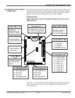
SYSTEM-40 BTU MEASUREMENT SYSTEM
1.3 STANDARD FEATURES AND SPECIFICATIONS (CONTINUED)*
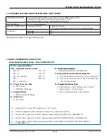
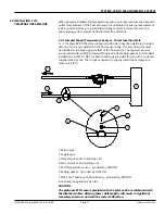
1.4 MODEL NUMBERING CODIFICATION
SYS-40 = Integral BTU Meter
AAA = Nominal Meter Size in Inches
E = Serial Communications
050 = ½”
130 = 1¼”
1 = RS485 (BACnet MS/TP or MODBUS RTU)
340 = ¾”
150 = 1½”
F = Analog & Pulse Input/Output Configuration
341 = ¾” High Flow
020 = 2”
2 = Two (2) Aux Pulse Inputs and One (1) Aux Pulse Output
2
010 = 1”
250 = 2½”
6 = One (1) Aux Pulse Input, One (1) Aux Pulse Output, and
011 = 1” High Flow
One (1) Analog Output
B = Process Connection Type
G = Temperature Sensor Type
0 = NPT Threads
0 = Direct Insertion - One (1) integral, one (1) remote
3
1 = ANSI Class 150 Flange
1
1 = Direct Insertion - Two (2) remote
4
C = Display/Interface
2 = Push in Thermowell Style - Two (2) remote
5
1 = IP65 Enclosure with Display
D = Input Power
0 = 24 V AC/DC
[1] Required for 2½” meter, NOT available on ½” to 2” meters
[2]
Default configuration, pulse inputs and outputs can be configured in the field
[3]
Valid for “AAA” meter size = 050-011. Requires reducer bushing INSTL4002-TSI or INSTL4004-TSI
[4]
Valid for “AAA” meter size = 050-011. Requires thermowell INSTL kit INSTL4001-TSD or INSTL4003-TSD
[5]
Valid for “AAA” = 340-250. Requires thermowell INSTL kit INSTL4005-TSD, INSTL4007-TSD, INSTL4008-TSD
or INSTL4009-TSD
Meter Model Number Coding = SYS-40-AAA-BCD-EFG
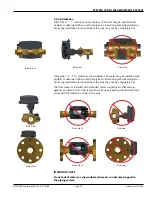
TEMPERATURE SENSORS
Field serviceable MID certified matched pair of 2-wire 1000Ω platinum RTDs
Calibrated to a differential measurement uncertainty of ±0.18°F
Meets EN1434/C900.1 accuracy requirements for 3K sensors
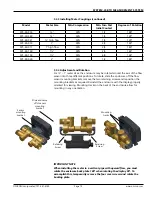
PIPE SIZE RANGE
½ - 2½” nominal diameter
PROCESS CONNECTIONS
AVAILABLE OPTIONS
• Male NPT threads
• 2½” meter provided with ANSI Class 150 raised face flanges
APPROVALS
NSF/ANSI
61
NSF/ANSI
372
*
Specifications subject to change without notice.