


ONICON Incorporated 727-447-6140
Page 14
www.onicon.com
SYSTEM-40 BTU MEASUREMENT SYSTEM
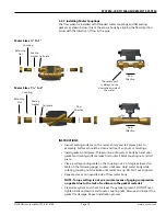
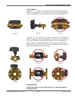
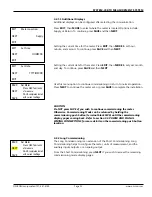
3.3.3 Installing Meter Couplings
The flow sensor is installed with threaded meter couplings and flat sealing
gaskets as shown below. Orient the sensor body by aligning the flow direction
arrow with the direction of flow in the pipe.
INSTRUCTIONS
• Inspect seating surfaces on the meter’s body and tail pieces prior to
assembly. Surfaces should be clean and free of any burs or markings.
• Install gasket in tail piece. Thread union onto meter’s body by hand until
gasket and mating surfaces make first contact. Mark coupling nut and tail
piece.
• Place a corresponding mark on the coupling nut, # of degrees (based on
table on the following page) counter clockwise. Hold meter body while
rotating coupling nut clockwise until marks line up. DO NOT over-tighten.
•
Repeat process on opposite side of flow meter body.
NOTE: Torque setting is not an accurate means of gaging compression
on gasket due to the lack of resilience in the gasket material.
•
Pressurize system and check for leaks. If any leak is present, DO NOT over-
tighten. Relieve pressure and loosen coupling nuts. Remove and inspect the
gasket for damage. Repeat installation process.
Retaining
Nut
Coupling
Sealing
Gasket
Tail piece
Meter Sizes ½" To 1"
Flow
Direction
The sensor port
is always on the
downstream side of
the meter.
Flow
Direction
Tail piece
Meter Sizes 11/4" to 2"
Retaining
Nut
Coupling
Sealing
Gasket
Flow
Direction