


ONICON Incorporated 727-447-6140
Page 32
www.onicon.com
SYSTEM-40 BTU MEASUREMENT SYSTEM
SECTION 5.0
AUXILIARY INPUTS
AND OUTPUTS
5.1 DETERMINING AUXILIARY
INPUTS AND OUTPUTS
CONFIGURATIONS
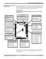
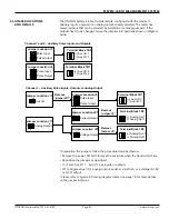
The ONICON System-40 can be configured to provide a variety of auxiliary
input and output combinations. The factory aux pulse input and output
configuration can be changed in the field by changing the jumper positions
for jumpers J1 – J3.
If the meter has been ordered with the analog output option, Jumper JP1 can
be used to configure the analog output as 4-20 mA or as a voltage output
(0-10 V or 0-5 V). Refer to the wiring detail on page 32 for jumper locations.
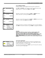
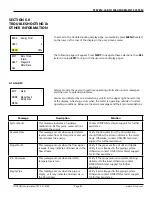
When configured for auxiliary pulse inputs, the System-40 will have the ability to
bring in local dry contact and open collector pulses which can be displayed by
the RS485 output.
The default description and communication via each auxiliary input is
“Counts.” Each pulse is a count of an accumulated value from the remote
device. The System-40 allows the user to change this description through
the commissioning process. See 4.2.2.3 AUXILIARY INPUT/ OUTPUT
CONFIGURATION SETTINGS for more information.
The local aux input description of the System-40 only appears on the LCD
display. The value transmitted over the RS485 network will be a unitless count,
regardless of the description programmed into the System-40. To reset the
auxiliary pulse input counts, please refer to the registers in the MODBUS
memory maps, located in section 8.0 MODBUS.
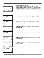
When configured for auxiliary pulse outputs, the System-40 will have the ability
to provide contact closure pulses for use with a remote totalizer or building
automation system. The System-40 allows the user to change this description
through the commissioning process. See 4.2.2.3 AUXILIARY INPUT/ OUTPUT
CONFIGURATION SETTINGS for more information.
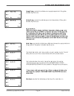
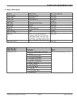
5.3.1 Single Mode Operation Pulse Outputs
The following pulse outputs are available from the System-40 when configured
for single mode operation in commissioning. Refer to 4.3.1 SINGLE MODE for
more information.
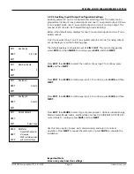
Total Volume
- Units match LCD totalizer. Output can be scaled for 1, 10, or
100.
Example: If configured for 10, the meter will require 10 LCD display
accumulations before a pulse output is provided.
Total Energy
- Units match LCD totalizer. Output can be scaled for 1, 10, or 100.
Example: If configured for 10, the meter will require 10 LCD display
accumulations before a pulse output is provided.
Mode Indication
- Latching output. The output will remain open when the
meter is in heating mode (supply temp. > return temp.) and will latch closed
when the meter is in cooling mode.
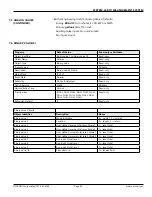
5.2 AUXILIARY INPUTS
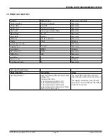
5.3 AUXILIARY OUTPUTS