


ONICON Incorporated 727-447-6140
Page 22
www.onicon.com
SYSTEM-40 BTU MEASUREMENT SYSTEM
SECTION 4.0
START-UP AND
COMMISSIONING
4.1 START-UP
4.2 COMMISSIONING
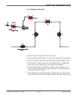
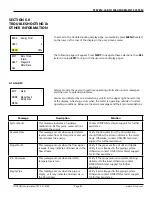
Part 1 Mechanical installation
Confirm that the flow sensor is properly located in the piping system (Sec. 3.1
& 3.3).
Confirm that the flow sensor is properly oriented with respect to flow
direction (Sec. 3.3.5).
Confirm that the temperature sensor(s) is properly located in the piping
system (Sec. 3.4).
Part 2 Programming
Confirm that the flow sensor location in the piping system (supply or return)
is programmed into the meter (Sec. 4.3).
Verify if the Serial Communication Setting (BACnet or MODBUS) in the meter
are correct (Sec. 4.2.1)
Verify that the Units of Measure Settings in the meter are correct (Sec. 4.2.2).
Confirm that there are no alarm indications and the meter is functional
(Sec. 6.0).
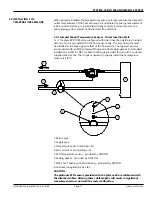
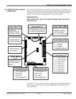
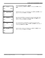
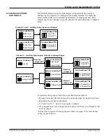
When power is first applied to the meter, the display will be illuminated, and the
following start screen will appear. Use the three pushbuttons on the left side of
the display to navigate the display pages and change settings.
Pressing
NEXT
, then
SEL
(select) will allow you to navigate the
Main Menu
display.
The System-40 BTU Meter is pre-programmed based on the specific application
and its' pipe size. The setting shown on the next page allows the installer to
commission the meter. Commissioning the meter is a two part process:
User Screens
– provide read-only information of the default meter configuration,
prior to meter commissioning, and meter run mode information after
commissioning. See section 4.3 USER SCREENS for additional information.
Commissioning Screens
– provide writeable display pages that allow the user to
properly configure the meter for the specific system and application in which it’s
being installed.
User Screens
Commissioning
NEXT
SEL
!
Main Menu