


ONICON Incorporated 727-447-6140
Page 6
www.onicon.com
SYSTEM-40 BTU MEASUREMENT SYSTEM
SECTION 1.0
INTRODUCTION
The purpose of this guide is to provide installation and commissioning
procedures, and basic operating and servicing instructions for the ONICON
System-40 BTU Meter.
WARNING
Only qualified service personnel should attempt to install or service this
product. Serious injury may result from the improper installation or use of
this product.
1.1 PURPOSE OF THIS GUIDE
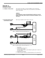
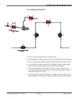
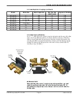
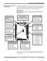
1.2 TYPICAL SYSTEM-40 BTU
METER INSTALLATION
Return
Supply
Supply
Return
BTU METER
SYSTEM-40
Made in USA
BTU/HR
49.50
BTU METER
SYSTEM-40
Made in USA
BTU/HR
49.50
Fan Coil
Unit or
Air
Handling
Unit
2
1
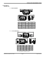
Figure 1: Installation Detail for Pipe Size Range from
½
- 1"
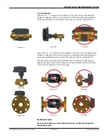
Figure 2: Installation Detail for Pipe Size Range from 1
¼
- 2
½
"
3
Supply Temp
2
1
3
4
Fan Coil
Unit or
Air
Handling
Unit
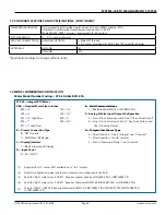
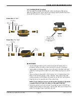
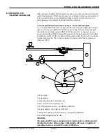
1. Input Power
20-28V AC/DC, 5 VA maximum
2. Input and output signals
Three (3) auxiliary signals can be configured as pulse inputs / outputs or as
an analog output
3.
RS485 BACnet or MODBUS
4.
Remote temperature sensor(s), installed downstream of flow meter body
Meter may be installed in either supply or return line.