


ONICON Incorporated 727-447-6140
Page 38
www.onicon.com
SYSTEM-40 BTU MEASUREMENT SYSTEM
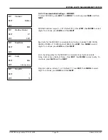
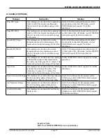
6.2 DIAGNOSTICS
Diagnostic provides the user with general operating information. From the
troubleshooting display, press
NEXT
and
SEL
(select)
Diagnostic
.
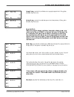
Signal Strength
provides the percentage of the flow transducer signal
amplifier’s automatic gain control operating level. Variable scaled from 0-90%.
65% - 90% : Good transducer signal
Reading < 65% : Poor tranducer signal. At this point, Signal Quality needs
to be verified.
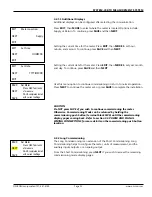
Signal Quality
provides the percentage between R1 (Automatic Gain Control)
and R2 (Factory Set-up Control). Factor % recommendation:
50% - 75% : Good transducer signal
10% - 49% : Poor transducer signal
Reading < 10%: Transducer signal is not functioning
Speed of Sound
is desirable to record the initial value at a defined temperature
during commissioning.
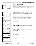
Transit Time
measure the difference in time from when a signal is transmitted
from one transducer until it crosses the pipe and is received by the other
transducer. The greater the difference, the faster the liquid is flowing.
Up = Against the flow
Down = With the flow
Highest Temp Display
provides the highest temperature measured by the meter
through the commissioning.
More Totals
!Alarm
Diagnostic
Meter Data
NEXT
EXIT
SEL
!
Signal Strength
0
0 = Epmty Pipe
NEXT
EXIT
MENU
Signal Quality
Gain R1=31 R2=30
Factor 0.0%
NEXT
EXIT
MENU
Speed of Sound
0000.000
ft/s
NEXT
EXIT
MENU
Transit Time
000.000Up
000.000Dn
NEXT
EXIT
MENU
Highest Temp Display
000.000
NEXT
EXIT
MENU
Deg F