3. On the base board, locate the appropriate Interface to connect the sensor. Next, unscrew
the nearest cable glands cap to said Interface, to allow sensors ends to enter into the Main
Unit.
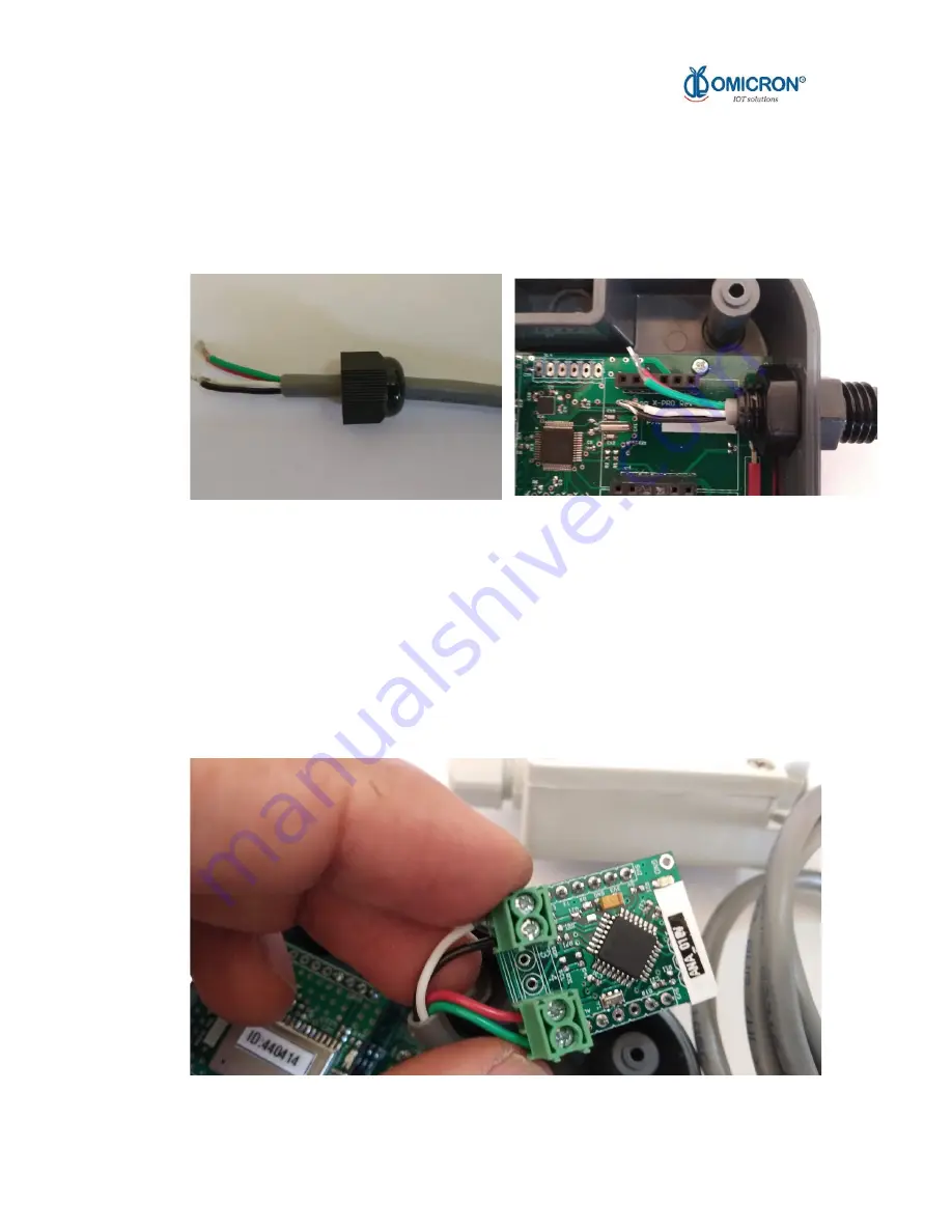
4. Before introducing the sensor terminals to the Main Unit through the cable gland, bear in
mind that the loosen cap must be inserted in the sensor cable as follows:
Figure B-4 Installation of the Cable
5. Introduce sensor ends into the Main Unit. It is recommended to let such sensor ends to
pass under the Interface board, as this would facilitate its connection.
6. Unscrew the necessary ports of the chosen Interface screw terminal, and then insert the
uncovered wires in their corresponding lines. To facilitate this task, each sensor end
should be tinned. To know in which order each end must be connected to said screw
terminal and consider the next pictures and the scheme in figures B-8 (valid for every
sensor Interface, please refers to the appendix C), and the port uses defined by the
Interfaces.
www.omicroning.co March 2020
45


