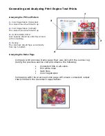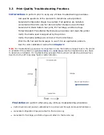
background image

 
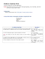
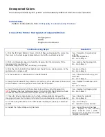
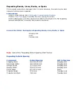
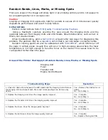
Background  


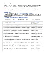
There is a very light covering of toner across the entire page. Background contamination 
can appear in one of the primary colors or gray. The printer displays no error code. 


Note 

Depending on the type of paper and environmental conditions, some light amount of 
random background spotting is normal. The whiter and glossier the paper, the more 
noticeable it will be. 


Initial Actions: 

 Perform Initial Actions from 

Print Quality Troubleshooting Practices


 Ask the customer about their typical printing habits. A high daily duty cycle can 

temporarily fatigue the OPC drums within the Imaging Unit and contribute to unwanted 
background toner. 


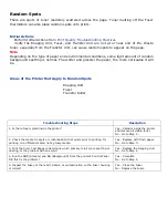
Areas of the Printer that Apply to Background Issues 
 

 Imaging Unit 

 Fuser  

 Transfer Unit 

 HVPS 

 Engine Control Board 


Troubleshooting Steps


Resolution


1. Is the printer in direct sun light? 


Yes – Move the printer. 

No - Go to Step 2. 


2. Does the background appear to be in only one of the primary colors? 


Yes – Go to Step 3. 

No - Go to Step 4. 


3. Check the Imaging Unit drum for toner contamination. Remove the Imaging 

Unit of the problem color. 
Is there a film of toner across the surface of the drum? 


Yes – Replace the Imaging Unit. 

No - Go to Step 4. 


4. Verify the printer is operating within its environmental specifications. Low 

humidity increases the degree of background toner. 


Yes – Go to Step 5. 

No - Advise the customer of the 

environmental specifications. 


5. Check the Transfer Unit belt. Is the background contamination a mixture of 

colors and excessive? 

Is the Transfer Unit belt contaminated with toner? 


Yes – Replace the Transfer Unit. 

No - Go to Step 6. 


6. Is the customer printing on high-gloss media? 


Yes – Advise the customer of the 
limitation of this printer. 

No - Go to Step 7. 


7. Check minimum clearances around the printer especially sides and back as it 

can cause heat buildup. 
Are clearances within specifications? 


Yes – Go to Step 8. 

No - Advise customer. 


8. Test the Fans. Heat build-up under the Imaging Units can cause toner to stain 

the background. 

Are the fans operating correctly? 


Yes – Go to Step 9. 

No - Replace the defective fan. 


9. Check that the Imaging Unit contacts are in working condition and clean. 


Yes – Clean the or replace the 

drum contacts. 

No - Go to Step 10. 


10. Remove the Imaging Units and the Transfer Unit and check for toner 
contamination on the high voltage contacts. 


Yes – Clean the contacts. 
No - Replace in the following 

order: Transfer Unit / HVPS 


Содержание C9800 Series

Страница 1: ...turer assumes no responsibility for the results of errors beyond its control While all reasonable efforts have been made to make this document accurate and helpful as possible we make no warranty of a...

Страница 2: ...tents Chapter 1 Printer Maintenance Procedures 1 1 Service Maintenance Procedures 1 2 Cleaning the Printer 1 3 Cleaning the Imaging Unit Contacts 1 4 Cleaning the LED Heads 1 5 Cleaning the Feed Rolle...

Страница 3: ...just Shut Down Admin Setup Admin Setup Calibration Exit Calibration Auto Density Mode Auto BG Adjust Mode Adjust Density Adjust Registration Setup Calibration Calibrate Remove Calibration Print Statis...

Страница 4: ...ity Troubleshooting Practices Light Prints in All Colors Light Print in Only One Color Blank Prints Mottled or Splotchy Prints Unexpected Colors Repeating Bands Lines Marks or Spots Random Bands Lines...

Страница 5: ...Chapter 4 Troubleshooting Paper Jams 4 1 Open Cover Paper Jam Tray X Side Cover 4 2 Open Cover Paper Jam Side Cover 4 3 Open Cover Paper Jam Top Cover 4 4 Paper Jam Duplex Unit...

Страница 6: ...r Fan Failure 121 Power Supply Fan Failure 127 Fuser 128 Fuser Belt 918 Duplex Fan Failure 181 919 Duplex Interface Failure 180 186 910 926 Tray 2 3 4 Com Errors 189 Inverter Unit Interface Failure 13...

Страница 7: ...tion loaded Kodak Calibration Pack Clean dry lint free cloth Black light protective bag Perform these routine maintenance procedures during the course of servicing the printer Clean the feed rollers e...

Страница 8: ...s 3 Turn off the printer 4 Clean all fans to remove excess dust 5 Ensure that all cover vents are clean and free of obstructions 6 Remove any debris or foreign objects from the Transfer Unit Fuser and...

Страница 9: ...LED Head with a clean lint free cloth 1 5 Cleaning the Feed Rollers Clean the accumulated dust from the Feed Rollers Caution Use care not to scratch or otherwise abrade the roller surface while clean...

Страница 10: ...Pages Print Pages Suspend Printing Resume Printing Print Secure Job Print Secure Job Menus Tray Configuration System Adjust Shut Down Admin Setup Admin Setup Calibration Exit Calibration Auto Density...

Страница 11: ...ray Finisher Count Item Description Staple Displays total pages stapled Punch Displays total pages punched Finisher Displays total pages ejected into the finisher Supplies Life Item Description Drum C...

Страница 12: ...er is 8 alphanumeric characters that can be assigned by a user Same as Asset Number of Menu Map CU Version Displays version no of CU Fiery Controller firmware Same as CU version of Menu Map PU Version...

Страница 13: ...PostScript font list PCL Font List Prints PCL emulation font list Demo Page Prints a demo page E mail Log Prints e mail log Usage Report Prints a usage report must be activated from the Print Statist...

Страница 14: ...fy a number of copies After specifying the number of copies press Enter to print all jobs with the specified number of copies Delete When you select Delete you are prompted to recheck by Yes No displa...

Страница 15: ...e is 2 00 to 2 00 mm Vertically Default is 0 00mm Duplex X Adjust During the flip side printing of duplex printing adjusts the position of the whole printing image 0 25 mm at a time Range is 2 00 to 2...

Страница 16: ...p Exits Setup Menu Server Setup See configuration sheet under Server Setup Network Setup See configuration sheet under Network Setup Parallel Setup See configuration sheet under Parallel Setup USB Set...

Страница 17: ...tion Auto BG Adjust Mode Off 1 0 1 2 Adjustment of the Auto Background Adjust Density Item Description Adjust Density Yes No Select yes to execute density adjustment Adjust Registration Item Descripti...

Страница 18: ...Screen Affects all Contin Yes No removes previous Calibration 12X6 Dot Screen Affects all Contin Yes No removes previous Calibration 12X6 Line Screen Affects all Contin Yes No removes previous Calibra...

Страница 19: ...ation ID Check Pattern and Engine Status of the Function Menu If this item is disabled the Print Information ID Check Pattern and Engine Status of the Function Menu is never displayed The printer is r...

Страница 20: ...n Arrow Scrolls down one menu item within a menu list Used to decrement data in tests requiring user input _____________________________________________________________________ Enter Enters the highli...

Страница 21: ...onds FACEDOWN SOLENOID Face Down solenoid ON OFF for 10 seconds EXIT SOLENOID Exit solenoid ON OFF for 10 seconds MPT LIFT UP Runs the MPT tray lift up motor MPT MOTOR Runs the MPT tray paper feed mot...

Страница 22: ...0 seconds INV SEPARATER Inverter Separator Clutch ON OFF for 10 seconds INV MOTOR B Runs the Inverter Motor B for 10 Seconds INV MOTOR A Runs the Inverter Motor A for 10 Seconds 2 5 Accessing the Swit...

Страница 23: ...ull Sensor Face down H Full L Empty Stacker Full Sensor Face up H Full L Empty Job Offset Paper End Sensor H ON L OFF Job Offset Home Pos Sensor H ON L OFF REG L R_ DENS_WEIGHT Alignment Left Sensor A...

Страница 24: ...Level H L 2nd Paper Size 4 Switch Port Level H L TRAY3 PE_PNE_CVO 3rd Paper End Sensor Port Level H L 3rd Paper Near End Port Level H L Cover Open 3rd Switch Port Level H L TRAY3 HOP_LIFT_FEED 3rd Ho...

Страница 25: ...the home position Feed roller home position Sensor H Home position L Not in the home position Paddle home position PI2 H Home position L Not in the home position FIN S17_S18_ S19_S20 Staple fold moto...

Страница 26: ...screen in order to execute the Adjust Density procedure 4 Next press the Down Arrow button down until Calibrate is highlighted and press the Enter button 5 In the Screen Setting window press the Down...

Страница 27: ...tor on Laptop 1 2 or 2 0 High Power for the ES 1000 Step 1 Setting up the Service Laptop to communicate with the printer Set up the Service Laptop computer via the crossover cable to the printer Step...

Страница 28: ...address and select Add If the device does not appear temporarily turn off all filtering Virus software on your laptop and try again The following screen will appear Select the watch icon and the Comm...

Страница 29: ...Select the Administrator Key and select Log In You have now successfully logged in to Command Workstation C9800 9800A3 192 168 XX XX...

Страница 30: ...Step 3 Setting up the ES 1000 Spectrophotometer...

Страница 31: ...Once installation is complete re launch Command Workstation...

Страница 32: ......

Страница 33: ......

Страница 34: ......

Страница 35: ......

Страница 36: ......

Страница 37: ......

Страница 38: ......

Страница 39: ......

Страница 40: ......

Страница 41: ......

Страница 42: ......

Страница 43: ......

Страница 44: ......

Страница 45: ......

Страница 46: ...ine See the Repeating Defects chart When a single component of the Imaging Unit is causing a print quality defect replace the Imaging Unit When analyzing a print quality defect first determine if the...

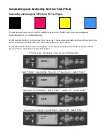
Страница 47: ...from the printer and to assist in troubleshooting The next section shows how to generate and analyze test prints 3 2 Generating and Analyzing Control Panel Test Prints Control panel test prints must...

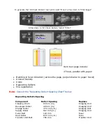
Страница 48: ...aper travel Uneven Density Voids Repeating Defects Mis registration Note Consult the Repeating Defect Spacing Chart below Repeating Defects Spacing Component Defect Spacing Replace Imaging Drum 94 mm...

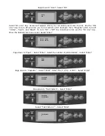
Страница 49: ...wering up the printer unit This may take up to 60 seconds The System Maintenance Menu will appear Down Arrow to Diagnostic Mode and press Enter Down arrow to Test Print and Select Enter Print Execute...

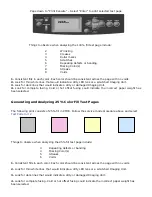
Страница 50: ...To turn On Off the individual colors use the On Line key Once the desired color menu is set Select Enter Page down to Page Select Enter Select the number of prints desired Select Enter Page down to Ca...

Страница 51: ...sing could indicate the incorrect paper weight has been selected Generating and Analyzing 25 Color Fill Test Pages The following print consists of 25 fill in CMYK Follow the service mode procedure abo...

Страница 52: ...l colors thin white lines dark lines Color registration Comparing with the previous Demo page will ensure consistent output that will match the customer s expectations 1 3 2 4 1 Color Registration Hor...

Страница 53: ...l Print the PS Test and Demo pages to see if it is an application problem Run the color calibration routine from Chapter 2 Note For troubleshooting purposes it is important to note the direction of pa...

Страница 54: ...ing Steps Resolution 1 Verify all packaging material has been removed form the toner cartridges Yes Go to Step 2 No Remove packing material 2 Remove the Imaging Units and the Transfer Unit and check f...

Страница 55: ...solated to one primary color Yes Go to Step 3 No Light Print in Only One Color 3 Remove the Toner Cartridge and check for toner starvation in the Imaging Unit Is there evidence of toner starvation Yes...

Страница 56: ...ere application and printer settings 2 Remove the Toner Cartridge and check for toner starvation inside the Imaging Unit Is there evidence of toner starvation Yes Replace the Toner Cartridge No Go to...

Страница 57: ...e loaded media Try different media to verify consistent reproducible problem Yes Go to Step 2 No Have the customer load approved media or correct the settings 2 Print the configuration page to verify...

Страница 58: ...No Go to Step 6 4 Is there debris or contamination on the LED Head Yes Clean them with a dry lint free cloth No Go to Step 5 5 Swap the LED Head of the problem color with any other LED Head Print a So...

Страница 59: ...to the Repeating Defects table Below to identify the problem component Areas of the Printer that Apply to Repeating Bands Lines Marks or Spots Imaging Unit Fuser Transfer Unit Note Consult the Repeati...

Страница 60: ...can also be associated with Cold Offset which lifts toner off the page in certain areas Usually this will occur in high coverage areas where the fuser temperature is not high enough to fuse the toner...

Страница 61: ...nter that Apply to Random Spots Imaging Unit Fuser Transfer Roller Troubleshooting Steps Resolution 1 Is there toner spilled inside the printer Yes Vacuum inside the printer and remove all visible ton...

Страница 62: ...of toner across the surface of the drum Yes Replace the Imaging Unit No Go to Step 4 4 Verify the printer is operating within its environmental specifications Low humidity increases the degree of bac...

Страница 63: ...from Print Quality Troubleshooting Practices Verify the correct media type is set at the Control Panel Print an internal test page to see if ghosting appears there as well Try printing with fresh med...

Страница 64: ...Media Thickness Sensor Troubleshooting Steps Resolution 1 Remove the Fuser covers and inspect for debris between the rollers Is there dirt or debris wrapped around or on the Fuser rollers Yes Replace...

Страница 65: ...Is the shutter functioning correctly Yes Go to Step 4 No Replace the solenoid and wiring harness 4 Inspect the Transfer Unit for tears or damage on the edges of the belt Is the belt damaged Yes Replac...

Страница 66: ...the problem color with any other LED Head Print a Supplies page Has the problem moved with the LED Head Yes Replace the defective LED Head No Go to Step14 14 Replace the Registration Sensor Board Did...

Страница 67: ...rify the printer is operating within its environmental specifications Yes Go to Step 3 No Advise customer on the specifications 3 Inspect the Transfer Unit Has the cleaning blade flipped or failing to...

Страница 68: ...gainst the paper Yes Go to Step 3 No Adjust the guides 3 Verify the size of media reported by the printer is the actual size Yes Go to Step 7 No Go to Step 4 4 Test the Paper Size Switches Run the Ser...

Страница 69: ...nit belt Troubleshooting Steps Resolution 1 Print the 100 Solid Fill Test print Is the problem with one primary color Yes Replace the defective Imaging Unit No Go to Step 2 2 Is the paper wrinkled dim...

Страница 70: ...or debris in the printer s paper path Yes Clean or remove obstructions No Go to Step 3 3 Clean the LED Heads with at dry lint free cloth Did this fix the problem Yes Complete No Go to Step 4 4 Remove...

Страница 71: ...rint the Color Test Pages Does the problem occur in one primary color Yes Replace the Imaging Unit of the defective color No Go to Step 2 2 Inspect the Transfer Unit Has the cleaning blade flipped or...

Страница 72: ...om the printers Control Panel Did this fix the problem Yes Complete No Go to Step 2 2 Are there any obstructions dirt or debris in the printer s paper path Check for toner spills Yes Clean and remove...

Страница 73: ...Chapter 4 Troubleshooting Paper Jams 4 1 Open Cover Paper Jam Tray X Side Cover 4 2 Open Cover Paper Jam Side Cover 4 3 Open Cover Paper Jam Top Cover 4 4 Paper Jam Duplex Unit...

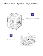
Страница 74: ...4 1 Open Cover Paper Jam Tray X Side Cover Squeeze the catch on tray X side cover 1 and open the cover Holding it by the tab 2 turn the paper guide outward 1 2...

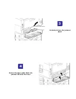
Страница 75: ...Return the paper guide back into position and close the cover Carefully remove the jammed paper 4 3...

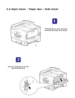
Страница 76: ...4 2 Open Cover Paper Jam Side Cover Pull the release lever 2 and open the side cover If the MP tray is open close it so that the side cover 1 is visible 2 1...

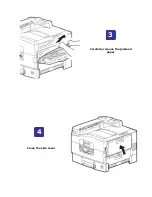
Страница 77: ...Close the side cover Carefully remove the jammed paper 4 3...

Страница 78: ...4 3 Open Cover Paper Jam Top Cover Squeeze the basket handle and raise the drum basket Squeeze the top cover handle 1 and open the top cover 1 2...

Страница 79: ...in the fuser unit push the lock lever 3 in the direction shown to release it Carefully remove any paper on the belt Holding the fuser unit 4 by the handle lift it out of the printer and place it on a...

Страница 80: ...Pull the jam release levers 5 and remove the paper Carefully replace the fuser unit into the printer and turn the lock lever in the direction shown to lock the fuser unit 7 6...

Страница 81: ...Open the side cover paper exit 8 and remove the jammed paper If paper is jammed near the paper exit open the face up stacker 7 9 8...

Страница 82: ...Close the side cover and then the face up stacker Return the drum basket 9 into position and check that it is locked 11 10...

Страница 83: ...Close the top cover and ensure that it is latched 12...

Страница 84: ...4 4 Paper Jam Duplex Unit Operate the duplex cover release lever 2 and open the duplex co e Carefully remove any jammed paper 1 2...

Страница 85: ...Operate the levers 3 and pull out the duplex unit Holding the front top cover by the grip 4 push it gently inwards and raise it 4 3...

Страница 86: ...In a similar manner check for and clear any jammed paper in the rear cover Remove any jammed paper 6 5...

Страница 87: ...Raise the front cover of the duplex unit Replace the two top covers 8 7...

Страница 88: ...Push the duplex unit back into position 9...

Страница 89: ...MM Replace RAM DIMM Replace Fiery PCB must move EEPROM to new board 032 CU Slot 2 DIMM RAM Check Error Re mount RAM DIMM Replace RAM DIMM Replace CU PCB must move EEPROM to new board 036 Slot 1 RAM Sp...

Страница 90: ...ntrol Board and Engine Board Replace CU PCB must replace EEPROM Replace PU PCB 073 to 075 Video Overrun Detected Check Connections Replace CU PCB must replace EEPROM 081 Parameter Match Check Error If...

Страница 91: ...or See Fuser Fan Failure page 111 128 Engine Fan Motor Error 01 Fuser Fan 02 Power Fan 03 PU Motor Fan 04 Belt Fan 05 ID Fan 06 Top Cover Fan See Fan Failure page 106 131 to 134 LED Head Error 131 Y H...

Страница 92: ...e Motor Driver Board Engine Control Board 189 Inverter Unit I F Error See Inverter Unit Interface Failure page 109 190 System Memory Overflow Replace CU PCB must replace EEPROM 200 to 202 PU Firmware...

Страница 93: ...2 C 353 K See ID Unit Life Error page 132 354 Fuser Life Error See Fuser Life Error page 133 355 Belt Life Error See Belt Life Error page 134 360 Double Side Printer Unit Error See Unsupported Duplex...

Страница 94: ...Tray5 Check Sensor Connections Replace Motor See Tray 1 2 3 4 Communication Errors page 108 917 Belt Slit Sensor Error Check Belt Unit is Turning Check Sensor Connections See Error in the Transfer Bel...

Страница 95: ...nual 096 01 Paper Eject Motor Error Check All Connections Check Replace Motor Replace Finisher Control PCB 096 02 Tray Raise Lower Error Replace Shift Motor Finisher Controller as a set Check Clean Re...

Страница 96: ...ce Error Check All Connections Check Replace Interface Cable Replace Finisher Control PCB Replace Engine PCB Self Diagnostic Error Codes Other Codes Code Cause Description Remedy 0101 to 0104 The data...

Страница 97: ...power 3 Check the Fiery Control Board LED s for a fault indication 4 Systematically remove all printer options to isolate a possible problem component Printer Continually Displays Warming Up or Initia...

Страница 98: ...g to the position of the tray s paper guides Upon installation of the tray the plate s position actuates the Paper Size Switch A Paper Size Mismatch error or Tray Missing error are sometimes the resul...

Страница 99: ...wer 3 Test wall Voltage Parts of the Printer that Apply 1 Fuser 2 LVPS 3 Engine Control Board Troubleshooting Procedure Steps Action Taken Yes No 1 Replace the Fuser Does the error persist Go to Step...

Страница 100: ...Board Troubleshooting Procedure Steps Action Taken Yes No 1 Test the Temp Humidity Sensor 1 Run the Scan Switch Test HUM_TEMP_OHP 2 Verify proper operation by blowing on the sensor Is the sensor opera...

Страница 101: ...e procedure below Parts of the Printer that Apply 1 Imaging Unit Motors 2 Motor Driver Board Troubleshooting Procedure Steps Action Taken Yes No 1 Test the cooling fans for proper operation and adequa...

Страница 102: ...w the procedure below Parts of the Printer that Apply 1 Engine Control Board EEPROM 2 Engine Control Board Troubleshooting Procedure Steps Action Taken Yes No 1 Cycle power to the printer Does the err...

Страница 103: ...e Printer that Apply 1 LVPS Troubleshooting Procedure Steps Action Taken Yes No 1 Visually inspect the LVPS for damage or excessive dust Is the LVPS damaged or dirty Clean the LVPS if dirty If damaged...

Страница 104: ...ken Yes No 1 Test the cooling fan for proper operation and adequate airflow Run the Motor Clutch Fan test Does the fan operate correctly Replace the Engine Control Board Go to Step 2 2 Check for 5 V t...

Страница 105: ...n Run the Motor Clutch Test FAN POWER Does the Fan operate correctly Replace the Engine Control Board Go to Step 2 2 Check the LVPS Fan connection Is the fan securely connected Go to Step 3 Reconnect...

Страница 106: ...of 30 minutes for cooling 4 Restart the printer 5 If the problem persists follow the procedure below 1 Fan Associated with the code 2 Engine Control Board Steps Action Taken Yes No 1 Test the cooling...

Страница 107: ...e the Duplex Unit If the error persists go to Step 2 2 Check all pins on the DUPLEX Wiring Harness for continuity Disconnect the DUPLEX Harness Is the DUPLEX Harness conductive Replace the Motor Drive...

Страница 108: ...below 1 High Capacity Feeder Control Board 2 Engine Control Board Steps Action Taken Yes No 1 Check the Hi Cap connector for damage Is the connector damaged Replace the connector Go to Step 2 2 Check...

Страница 109: ...r Cord Is there any damage Replace any damaged parts Go to Step 2 2 Check the Inverter connection Is the Inverter interface cable securely connected at both ends Go to Step 3 Connect the Inverter to t...

Страница 110: ...p 2 2 Ensure the LED Head harness is properly connected and not damaged Is the wiring harness defective Reconnect or replace the wiring harness Go to Step 3 3 Check harness continuity between the LED...

Страница 111: ...ol Board Steps Action Taken Yes No 1 Test the cooling fan for proper operation and adequate airflow Run the Motor Clutch Fan test Does the fan operate correctly Replace the Engine Control Board Check...

Страница 112: ...e procedure below 1 Fuser 2 Engine Control Board Steps Action Taken Yes No 1 Ensure the proper Fuser 110v vs 220v is installed in the printer Is the correct Fuser installed Replace the Engine Control...

Страница 113: ...e Duplex Connector Is there any damage Replace any damaged parts Go to Step 2 2 Check that the Duplex Unit is correctly installed and fully seated Go to Step 3 Reseat the Duplex Unit 3 Check the Duple...

Страница 114: ...1 Test the Fuser fuse Is the Fuse Cut Replace the Engine Control Board Go to Step 2 2 Replace the Fuser Cycle the power Does the error persist Go to Step 3 Complete 3 Check all pins of the harness bet...

Страница 115: ...the Fuse cut Replace the Engine Control Board Go to Step 2 2 Check the connections between HVPS HVPS Cover and Transfer Unit Are the contacts clean and intact Install a new Transfer Unit and verify t...

Страница 116: ...trol Board Steps Action Taken Yes No 1 Check the affected Imaging Drum Unit contacts for evidence of fault or damage Is there any damage debris or corrosion Replace the damaged parts Go to Step 2 2 Te...

Страница 117: ...Board Steps Action Taken Yes No 1 Cycle power to the printer Does the error persist Go to Step 2 Complete 2 Reseat the Fiery Control Board to the Engine Board Does the error persist Replace the Engin...

Страница 118: ...nterface Cable Power Cord Finisher connections Is there any damage Check the following for evidence of fault or damage Finisher Interface Cable Finisher connections Is there any damage Go to Step 2 2...

Страница 119: ...wer Cord Inverter Power Supply Is there any damage Replace any damaged parts Go to Step 2 2 Check AC Power Is the AC voltage available at the outlet Go to Step 3 Advise customer 3 Check the Inverter c...

Страница 120: ...n Is the Control Panel Harness connected to the Engine Control Board Go to Step 2 Connect the Control Panel harness 2 Check all pins on the Control Panel Harness for continuity Disconnect the harness...

Страница 121: ...Interlock Switches for the test 2 Run the Motor Clutch test to test the Transfer Belt Motor Does the motor operate Replace the Transfer Unit If the error persists go to Step 3 Replace the motor If th...

Страница 122: ...it Lift Up Down Mechanism Is there any damage Replace any damaged parts Go to Step 2 2 Test the Drum Phase Sensor Run the Scan Switch test for the indicated Imaging Unit Does the sensor function corre...

Страница 123: ...go to Step 6 Check the Up Down Mechanism and associated gears See Drive Motors for a description of Up Down Mechanism operation 1 Access the Cyan Unit Motor 2 Rotate the Cyan Motor manually in both di...

Страница 124: ...U Flash Memory 248 Inverter Flash Memory 1 Cycle the printer s power 2 If the problem persists follow the procedure below 1 Engine Control Board Steps Action Taken Yes No 1 Cycle power to the printer...

Страница 125: ...ntrol Board Steps Action Taken Yes No 1 Check for evidence of fault or damage to the indicated unit Is there damage evident Replace any damaged parts Go to step 2 2 Go to Step 3 3 Replace the Engine C...

Страница 126: ...t the affected Toner Motor 1 Remove the Toner Cartridge 2 Run the motor Clutch test to test the Toner Supply Motor test Does the motor rotate Go to Step 3 Replace the motor If the error persists repla...

Страница 127: ...Test the Registration Motor Run the Motor Clutch test to test the motor Is the motor operating correctly Replace the MPT Assembly Replace the Registration Motor 3 Test the MPT Home Position Sensor Run...

Страница 128: ...up any compacted toner Reinstall the cartridge Does the error persist Go to Step 3 Complete 3 Check the RFID Harness continuity 1 Remove the Top Cover 2 Disconnect the RFID cable from the RFID and on...

Страница 129: ...Step 2 Replace the Engine Control Board 2 Test the Up Down Motor 1 Remove the Image Drum Units 2 Run the motor Clutch test to test the Up Down Motor Does the motor rotate Does the Up Down mechanism m...

Страница 130: ...Go to Step 2 2 Test the Top Cover Interlock Switch Run the Scan Switch test to test the Switch Does the switch function correctly Replace the Engine Control Board Go to Step 3 3 Replace the Top Cover...

Страница 131: ...age Fuser Fuser Connector Fuser Release Sensor Is there any damage Replace any damaged parts and then cycle printer power Replace the Fuser If the error persists Go to Step 2 2 Test the Fuser Release...

Страница 132: ...sts follow the procedure below 1 C M Y K Imaging Unit 2 Engine Control Board Steps Action Taken Yes No 1 Generate a Configuration Page and check the indicated Drum Life counter under Supply Life Does...

Страница 133: ...w 1 Fuser Unit 2 Engine Control Board Steps Action Taken Yes No 1 Generate a Configuration Page and check the indicated Fuser Life counter under Supply Life Does the counter indicate end of life Repla...

Страница 134: ...1 Transfer Unit 2 Engine Control Board Steps Action Taken Yes No 1 Generate a Configuration Page and check the indicated Belt Life counter under Supply Life Does the counter indicate end of life Repla...

Страница 135: ...Oki Toner Cartridge is installed Go to Step 3 Complete 3 Check all pins of the RFID Harness for continuity Remove the Top Cover Disconnect the RFID cable from the RFID reader board and the Engine Con...

Отзывы: