Pos.
Item
Pos.
Item
1
Servomotor
4
Shaft coupling aligning screw and
clamping screw
2
Servomotor fixing screw
5
Butterfly valve DMK-Q
3
Shaft coupling
6
Aligning surface of servomotor’s shaft
1. Disconnect the cables according to the instructions.
2. Loosen the clamping and aligning screw of the shaft coupling (shaft coupling stays
on butterfly valve’s shaft)
3. Detach the servomotor fixing screws and remove the servomotor.
4. Fix the new servomotor to the shaft coupling.
5. Check first that the shaft coupling aligning screw is at engine shaft level.
6. Tighten the clamping screw.
7. Tighten the servomotor fixing screws.
8. Connect the cables according to the instructions.
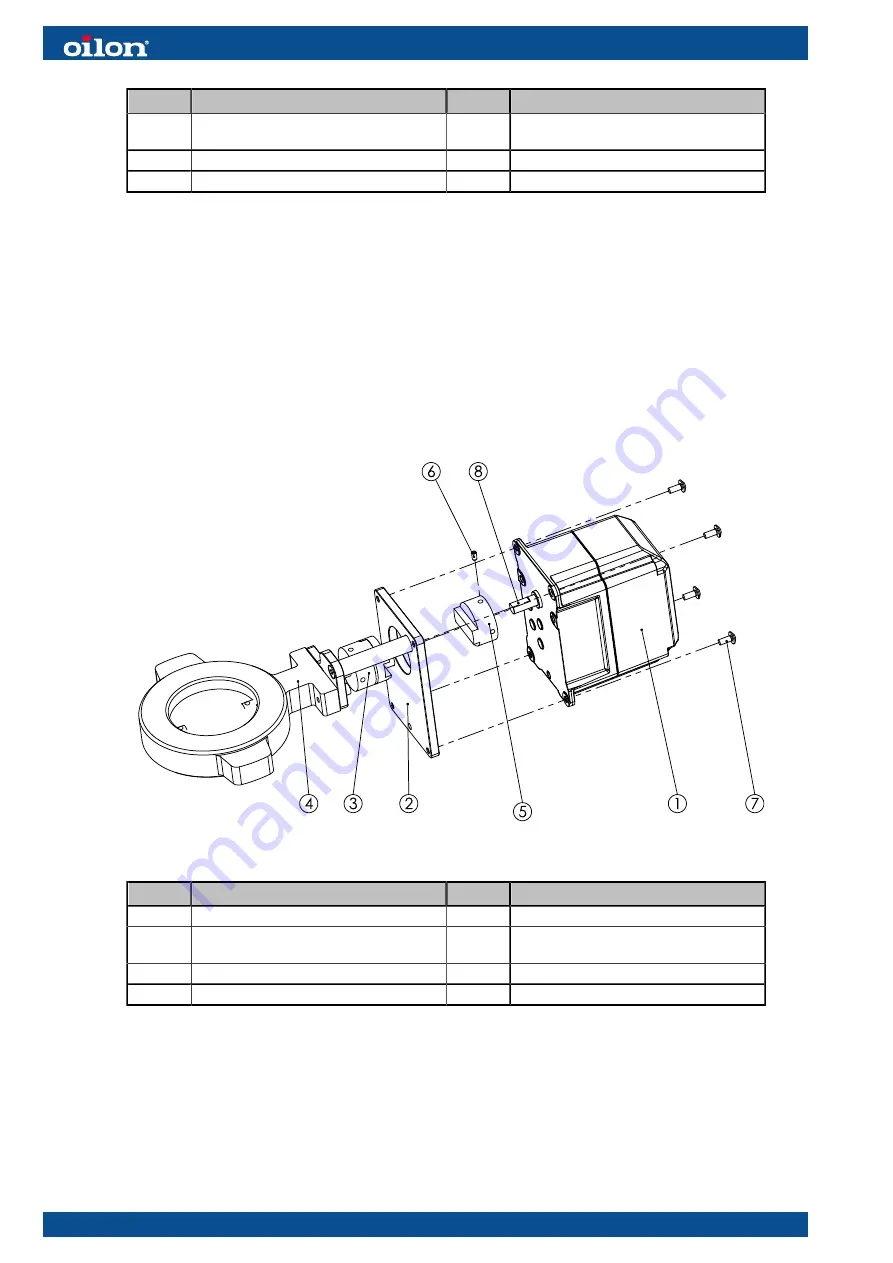
Servomotor of gas butterfly valve VKF41
D033571 ver. 1
Pos.
Item
Pos.
Item
1
Servomotor
5
Motor side of shaft coupling
2
Servomotor’s holder
6
Shaft coupling clamping screw (M5x8
din913)
3
Shaft coupling
7
Servomotor fixing screw
4
Regulating valve
8
Shaft’s aligning surface
1. Disconnect the cables according to the instructions.
2. Loosen the servomotor fixing screws; the shaft coupling half stays on motor shaft.
3. Loosen the clamping screw of the shaft coupling half and remove it from motor
shaft.
4. Fix the new servomotor to the shaft coupling.
5. Check that the shaft coupling half goes down to bottom on motor shaft.
6. Check that the shaft coupling clamping screw is aligned with the motor shaft
surface. Tighten the screw.
110 (129)
M5178 1647EN
Содержание GKP-350 M
Страница 2: ......
Страница 5: ...6 15 Burner part list 129 M5178 1647EN 3 129...
Страница 6: ...4 129 M5178 1647EN...
Страница 18: ...Block diagram of contact links Block diagram ver 5 16 129 M5178 1647EN...
Страница 100: ...5 5 Time sequence diagram gas use Time sequence diagram G ver 3 98 129 M5178 1647EN...
Страница 101: ...Time sequence diagram Gp1 ver 5 M5178 1647EN 99 129...
Страница 132: ...130 129 M5178 1647EN...
Страница 133: ......


