Output Wiring:
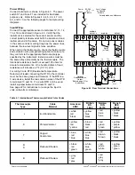
Four different types of output devices can be used from
output one. Relay, current, voltage and pulsed voltage
provide a variety of control applications, Verify that the
output device is correctly selected to meet your
application requirements and make certain the ratings
of the output devices are not exceeded before wiring
the system.
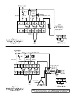
The external connections depend on what type of
output is installed. Pulsed voltage output is not
isolated from the internal circuits of the instrument.
Sensor Placement
Proper sensor placement can eliminate many problems
in a control system. The probe should be placed so
that it can detect any temperature change with minimal
thermal lag. In a process that requires fairly constant
heat output, the probe should be placed close to the
heater. In processes where the heat demand is
variable, the probe should be closer to the work area.
Some experimenting with probe location is often
required to find this optimum position.
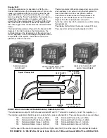
In a liquid process, addition of a stirrer will help to
eliminate thermal lag. Since the thermocouple is
basically a point measuring device, placing more than
one thermocouple in parallel will provide an average
temperature reading and produce better results in most
air heated processes.
Proper sensor type is also a very important factor in
obtaining precise measurements. The sensor must
have the correct temperature range to meet the
process requirements. In special processes the sensor
might have to have different requirements such as
leak-proof, anti-vibration, antiseptic, etc.
Standard thermocouple sensor limits of error are ± 4
degrees F (±2 degrees C) or 0.75% of sensed temper-
ature (half that for special) plus drift caused by improp-
er protection or over-temperature occurance. This
error is far greater than controller error and cannot be
corrected at the sensor except by proper selection and
replacement.
(Red) –
+
T/C
1
2
3
4
5
6
7
8
9 10 11 12 13 14 15 16
OUT 1
Power Input
ALM 1
ALM 2
Load
3A/240VAC
Max
Hot
Fuse
Neutral
Alarm, Lights or
other Devices
Fig. 4.10
Dwell Function
When installation has been completed, the clear protective
film can be removed from the faceplate.
12 13 14
A
B
B
3-Wire
RTD Connection

