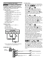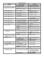
Table 5.5 Engineering Level
The engineering level can be entered at any time by
pressing the keys. This level contains six
parameters for control configuration and options. The
parameters are defined as:
Manual Mode (hand control) – This feature is used if
the sensor fails. The control can now be used as an
on-off proportional timer to control the load until a new
sensor can be installed. The setting for heating or cool-
ing is 0 - 100% of the proportional cycle time.
Peak Process Values – The minimum and maximum
peak values of the process are indicated here.
Calibrate A-D Converter – This parameter is used
during the calibration procedure.
Fail Safe – This defines the status of the outputs if the
sensor fails.
Lock Parameters – Levels 0, 1 or 2 in the operators
level can be locked-out to prevent unauthorized
tampering.
Configuration Level – This feature allows parameters
to change levels (0, 1 or 2) in the operators level. The
purpose of this is to allow only selected parameters to
be adjustable and all the others to be locked-out. For
example, if only the set point is to remain un-locked, all
the other parameters in level 0 can be moved to level 1.
Then lock out level 1 and 2.
Press the keys to exit the engineering level.
Manual Mode
(hand control).
Used if
sensor fails.
Peak Process
Value. Stored
minimum and
maximum values.
Calibrate
A-D Converter
Indicates the percentage
power of output 1. (Heating)
Long
Long
Indicates the percentage
power of output 2. (Cooling)
or
Indicates the maximum (peak) process value.
Indicates the minimum (peak) process value.
or
or
or
Adjusts the Cold junction compensation code.
(Range -19.9 to 42.7)
Adjusts the Drift compensation code.
(Range -6.6 to 6.6)
The percentage of on-time for output 1 can be
adjusted by using the keys. Range: 0 - 100%
(Not functional with ETR-9200)
Long
Long
Resets the maximum process value.
Resets the minimum process value.
Long
Long
Long
Calibrate the A-D converter and enter
the Cold-Junction compensation code.
Calibrate the 0
4-20mA and enter it.
Enter the drift compensation code
(Also note the calibration procedure on page 23.)
(Continued on next page)

